Power Profile Kit II doesn't show current value when it is testing the current in GND

I am testing the current consumption of SIM cards with PPK2.


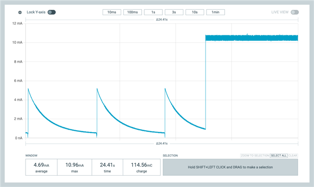
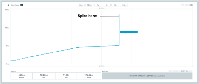
When PPK2 is connected to VCC ( voltage 1.8 v or 3 v ), the PPK2 can display the current properly ( around 9 mA ).


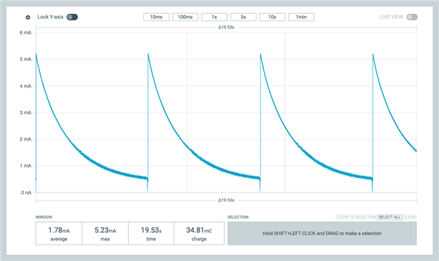
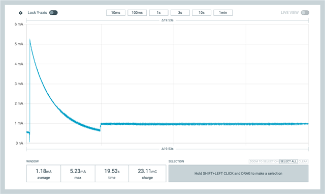
But when PPK2 is connected to GND ( voltage 0 ), the PPK2 cannot display the current properly ( display as 1 mA, but actually it should be 9 mA ). With oscilloscope I can see correct current value.

PPK2 current measurement cannot work properly in low voltage?

Application Version is 4.1.2

Parents
  • Hello,

    Could you perhaps share a picture of your set-up/the connections that you made.?

    Regards,

    Swathy

  • Hi,

    I found I can reproduce this issue in a simple setup.

    Use a 5V power and 500 ohm resistor.

    If connect in this way ( connection_type_01 )

    Power 5V --> 500 ohm resistor --> PPK2 VIN --> PPK2 VOUT --> Power GND, you will see the following wave, sure the current is wrong ( should be 10 mA )

    Then if you connect PPK2 GND ( near the PPK2 VOUT ) to GND, you can get good wave, but the current is only 1 mA, which is not correct, should be 10 mA.

    See the test result:

    If connect in this way ( connection_type_02 )

    Power 5V --> PPK2 VIN --> PPK2 VOUT--> 500 ohm resistor --> Power GND

    Without connect PPK2 GND to Power GND, the test result is similar to connection_type_01.

    But when PPK2 GND is connected to Power GND, the result is OK, it shows the current is around 10 mA.

    So the PPK2 GND is useful for testing, if the PPK2 GND and PPK2 VOUT both connect to Power GND (connection_type_01 case), the result is not correct.

Reply
  • Hi,

    I found I can reproduce this issue in a simple setup.

    Use a 5V power and 500 ohm resistor.

    If connect in this way ( connection_type_01 )

    Power 5V --> 500 ohm resistor --> PPK2 VIN --> PPK2 VOUT --> Power GND, you will see the following wave, sure the current is wrong ( should be 10 mA )

    Then if you connect PPK2 GND ( near the PPK2 VOUT ) to GND, you can get good wave, but the current is only 1 mA, which is not correct, should be 10 mA.

    See the test result:

    If connect in this way ( connection_type_02 )

    Power 5V --> PPK2 VIN --> PPK2 VOUT--> 500 ohm resistor --> Power GND

    Without connect PPK2 GND to Power GND, the test result is similar to connection_type_01.

    But when PPK2 GND is connected to Power GND, the result is OK, it shows the current is around 10 mA.

    So the PPK2 GND is useful for testing, if the PPK2 GND and PPK2 VOUT both connect to Power GND (connection_type_01 case), the result is not correct.

Children
  • The strange things is why AMP mode need to connect 3 lines then can measure current ( VIN and VOUT can understand, GND not sure what is the usage in AMP mode). When I use multimeter to test current, only need to connect two lines then can get result.

  • The PPK2 is based on a nRF52840 which has no current measurement feature, only voltage measurement via the internal SAADC. The internal code is not released, but this may be ether a single-ended or a differential measurement. Current I = (VIN-VOUT)/Rc where Resistor Rc for current sense is 1k0 in parallel with one or more of 110R, 11R0, 1R0 and 0R051 for the different measurement ranges. The nRF52840 SAADC may not perform well when measuring an input voltage connected to GND, which might give erroneous results for current if not compensated for in the software (which we do not have details of). The PPK2 is designed to measure current in the load on VOUT, not on the load on VIN; connection type 2 with VIN->500R->GND is correct provided the GNDS are all common.

    // Resistor Rc for current sense is 1k0 in parallel with one or more of 110R, 11R0, 1R0 and 0R051
    //
    //              <- +ve Supply to DUT From VOUT                               External Battery +ve To VIN
    //             +------------------------------+                             +-----------------------+
    //             |                              |                             |                       |
    //             |              +---------+     |                             |     +---------+       |
    //             |              |     GND |     | VOUT                   VIN  |     | GND -ve |       |
    //   +=========O=========+    |    +====O=====O=============================O=====O====+    |       | Battery
    //   |        Vdd (+)    |    |    |    |     #----+                        |     |    |    |       | + 3 volts
    //   |                   |    |    |    |     |    |Rc        AMPERE \      |     |    |    |     +-O-+
    //   |                   |    |    |    |     |   +++                 \     |     |    |    |     |   |
    //   |                   |    |    |    |     |   | |   +-----------O  O----#     |    |    |     |   |
    //   | Device Under Test |    |    |    |     |   | |   |                   |     |    |    |     |   |
    //   |       DUT         |    |    |    | 120k|   | |   |                   |120k |    |    |     |   |
    //   |                   |    |    |    |    +++  +++   |   \  SOURCE      +++    |    |    |     |   |
    //   |                   |    |    |    |    | |   |    |    \             | |    |    |    |     +-O-+
    //   |                   |    |    |    |    | |   +----#--O  O-- PPK LDO  | |    |    |    |       | Gnd (-)
    //   |                   |    |    |    |    | |                           | |    |    |    +-------+
    //   |                   |    |    |    |    +++                           +++    |    |
    //   |                   |    |    |    |     |                             |     |    |
    //   |                   |    |    |    |     #-- VDUT                VIN --#     |    |
    //   |                   |    |    |    |     |  Sense                Sense |     |    |
    //   |                   |    |    |    |    +++                           +++    |    |
    //   |                   |    |    |    |    | |                           | |    |    |
    //   |                   |    |    |    |    | |                           | |    |    |
    //   |                   |    |    |    |    | |                           | |    |    |
    //   |                   |    |    |    |    +++                           +++    |    |
    //   |                   |    |    |    |     | 30k                     30k |     |    |
    //   |                   |    |    |    +--#--+                             +--#--+    |
    //   |                   |    |    |       |                                   |       |
    //   |                   |    |    |     =====      <<== Common Gnd ==>>     =====     |
    //   |                   |    |    |      ===           (Common -ve)          ===      |
    //   |        Gnd (-)    |    |    |       =                                   =       |
    //   +=========O=========+    |    +===================================================+
    //             |              |     PPK-II
    //             +--------------+

  • I tested with the following setup.

    Power VCC (5V) --> 500 ohm resistor (R1) --> PPK2 VIN --> PPK2 VOUT --> 0 to 100 ohm adjustable resistor (R2)  --> GND

    The R2 is used to avoid the voltage of PPK2 VOUT is same as GND, then the test result will not be correct.

    While adjusting R2 from 0 ohm to 100 ohm, it seems that when R2 is increasing, the PPK2 test result will become more accurate, then at around R2 is 470 ohm and the PPK2 VOUT is 0.442 V, the test result will be correct. You can see there is spike in the wave form, after that spike, the test result is correct.

    Can you check why there is a spike? Also any workaround for this PPK2 wrong test result? If no workaround then need to at least give user a warning that if PPK2 VOUT is less than 0.442 V ( Or some more accurate value you can get), the test result may not be correct.

    Because some users may assume PPK2 test result is correct and use that data as reference then it may cause issue. ( If they don't use multimeter or oscilloscope to double confirm ).

    For this static current case, use multimeter can double confirm. But for dynamic current case, need to use oscilloscope and some resistor to double check. It needs extra work. If can correct in PPK2 level it will be better. If cannot, need to tell the user the limitation of the PPK2 current measurement.

  • My best guess is that VDUT - which is the measurement of VOUT using a 120k and 30k resistor divider - gives a VDUT voltage of 88mV when VOUT is 0.442V and 88mV is close to nothing and subject to issues, especially when reducing further as R2 is decreased. I imagine Nordic would simply say - quite reasonably, in my humble opinion - that this is outside the specification of the PPK2 which is designed to measure the current consumption of nRF parts in operation, which don't work at all below a volt or so; the PPK2 was never intended to be a general purpose multimeter.

    As an aside, given that the PPK2 measures the DUT voltage VOUT, it would be most useful if that value were available as several users in this forum have requested. Nordic?

    Edit: I forgot to add the specification, which as you say is needed; Nordic defines minimum voltage (on VIN input) as 0.8V: "For the ampere meter mode, an external power supply must source VCC levels between 0.8 and 5V to the device under test (DUT). For the source mode, the PPK2 supplies VCC levels between 0.8 and 5V and the on-board regulator supplies up to 1A of current to external applications."

    Power-Profiler-Kit-2

Related