Unable to perform IQ sampling normally

SW version :2.4.0
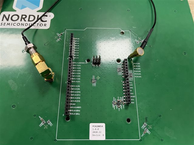
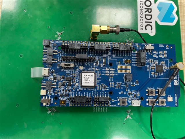
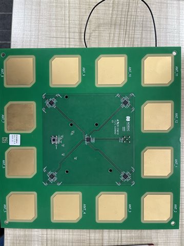
HW revision: nRF52833 development board, PCA20054 Direction Finding Antenna Board 1_0_0
I use the routine director_finding_central  and  director_finding_periopheral for IQ sampling, and can obtain IQ sampling data.
When I put the original
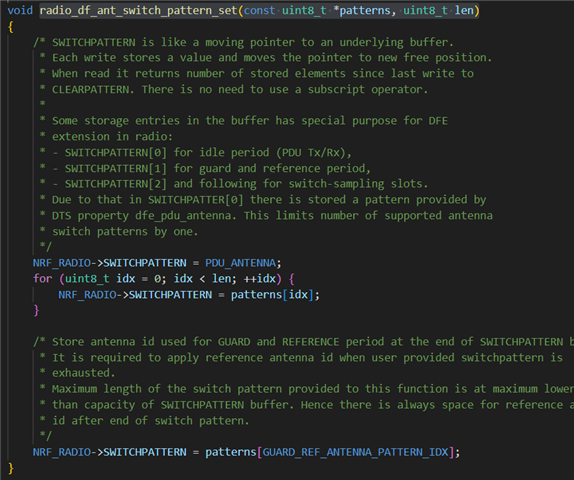
static const uint8_t ant_patterns[] = { 0x2, 0x0, 0x5, 0x6, 0x1, 0x4,
0xC, 0x9, 0xE, 0xD, 0x8, 0xA };
Change to
static const uint8_t ant_patterns[] = { 0xC, 0x9, 0xE, 0xD, 0x8, 0xA,
0x2, 0x0, 0x5, 0x6, 0x1, 0x4 };
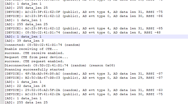
The Bluetooth connection will disconnect, making it impossible to perform normal IQ sampling.
May I ask why this situation has occurred?


Below is the serial port output

Parents
  • Hi

    Have you set this custom antenna pattern on both sides of the connection or just on the central side? How have you connected the antenna array to the nRF52833 DK on your end? The different antennas are connected to specific antenna switches, so they need to match in order to switch correctly. So when you change the antenna pattern without changing the switch pattern they won't match and likely cause these CRC errors. Is there a specific reason you're playing around with the antenna switching patterns here?

    Best regards,

    Simon

  • Have you set this custom antenna pattern on both sides of the connection or just on the central side?

    I use AOA  mode and just set this custom antenna pattern on the central side

    How have you connected the antenna array to the nRF52833 DK on your end?

    Pin Header,  I will upload a picture later to show the connection

    So when you change the antenna pattern without changing the switch pattern they won't match

    the antenna pattern is passed as a parameter to this interface,so the switch pattern will change according to the antenna pattern

    Is there a specific reason you're playing around with the antenna switching patterns here?
    We want to use our own Antenna Board and antenna pattern,   so we need to verify different antenna switching patterns. 
    According to the code process,
    changing the value of static const uint8_t ant_catterns will also change the SWITCHPATTERN register, so I hope to confirm with you whether changing the antenna switching patterns can still obtain IQ sampling values normally
    To describe it accurately, I will explain it in Chinese
    我们打算使用我们自己设计的天线,天线切换的顺序也是我们自己定义的,所以我们想用 nRF52833 DK 和  PCA20054  Antenna Board 做验证,看看天线切换的顺序是否可以改变,但是现在我们改变天线切换顺序,板子的连接都不正常了。
    根据代码流程, 改变  static const uint8_t ant_patterns 的值,  SWITCHPATTERN 寄存器也会跟着改变,所以希望和你们确认,改变天线的切换顺序是否还能正常获取IQ采样值
Reply
  • Have you set this custom antenna pattern on both sides of the connection or just on the central side?

    I use AOA  mode and just set this custom antenna pattern on the central side

    How have you connected the antenna array to the nRF52833 DK on your end?

    Pin Header,  I will upload a picture later to show the connection

    So when you change the antenna pattern without changing the switch pattern they won't match

    the antenna pattern is passed as a parameter to this interface,so the switch pattern will change according to the antenna pattern

    Is there a specific reason you're playing around with the antenna switching patterns here?
    We want to use our own Antenna Board and antenna pattern,   so we need to verify different antenna switching patterns. 
    According to the code process,
    changing the value of static const uint8_t ant_catterns will also change the SWITCHPATTERN register, so I hope to confirm with you whether changing the antenna switching patterns can still obtain IQ sampling values normally
    To describe it accurately, I will explain it in Chinese
    我们打算使用我们自己设计的天线,天线切换的顺序也是我们自己定义的,所以我们想用 nRF52833 DK 和  PCA20054  Antenna Board 做验证,看看天线切换的顺序是否可以改变,但是现在我们改变天线切换顺序,板子的连接都不正常了。
    根据代码流程, 改变  static const uint8_t ant_patterns 的值,  SWITCHPATTERN 寄存器也会跟着改变,所以希望和你们确认,改变天线的切换顺序是否还能正常获取IQ采样值
Children
No Data
Related