
I have an array of LEDs on my custom board. One of the LEDs is set on a UART0 RTS pin, which is GPIO(0,5), and we are using ground as common. To avoid any conflicts, I disabled the UART0 node in my overlay file, but this LED still glows before any other LED.
&pwm0 {
status = "okay";
};
&spi1 {
status = "disabled";
};
&spi3 {
status = "disabled";
};
&i2c1 {
status = "disabled";
};
&pwm1 {
status = "okay";
pinctrl-0 = <&pwm1_default>;
pinctrl-1 = <&pwm1_sleep>;
pinctrl-names = "default", "sleep";
};
&pwm2 {
status = "okay";
pinctrl-0 = <&pwm2_default>;
pinctrl-1 = <&pwm2_sleep>;
pinctrl-names = "default", "sleep";
};
&pwm3 {
status = "okay";
pinctrl-0 = <&pwm3_default>;
pinctrl-1 = <&pwm3_sleep>;
pinctrl-names = "default", "sleep";
};
&uart1 {
status = "disabled";
};
&arduino_header {
gpio-map = <0 0 &gpio0 3 0>,
<1 0 &gpio0 4 0>,
<2 0 &gpio0 28 0>,
<3 0 &gpio0 29 0>,
<4 0 &gpio0 30 0>,
<5 0 &gpio0 31 0>,
<6 0 &gpio1 1 0>,
<7 0 &gpio1 2 0>,
<8 0 &gpio1 3 0>,
<9 0 &gpio1 4 0>,
<10 0 &gpio1 5 0>,
<11 0 &gpio1 6 0>,
<12 0 &gpio1 7 0>,
<13 0 &gpio1 8 0>,
<14 0 &gpio1 10 0>,
<15 0 &gpio1 11 0>,
<16 0 &gpio1 12 0>,
<17 0 &gpio1 13 0>,
<18 0 &gpio1 14 0>,
<19 0 &gpio1 15 0>,
<20 0 &gpio0 26 0>,
<21 0 &gpio0 27 0>;
};
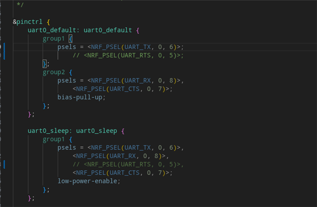
&pinctrl {
uart0_default: uart0_default {
group1 {
psels = <NRF_PSEL(UART_TX, 0, 6)>;
// <NRF_PSEL(UART_RTS, 1, 12)>;
};
group2 {
psels = <NRF_PSEL(UART_RX, 0, 8)>,
<NRF_PSEL(UART_CTS, 0, 7)>;
bias-pull-up;
};
};
uart0_sleep: uart0_sleep {
group1 {
psels = <NRF_PSEL(UART_TX, 0, 6)>,
<NRF_PSEL(UART_RX, 0, 8)>,
// <NRF_PSEL(UART_RTS, 1, 12)>,
<NRF_PSEL(UART_CTS, 0, 7)>;
low-power-enable;
};
};
pwm0_default: pwm0_default {
group1 {
psels = <NRF_PSEL(PWM_OUT0, 0, 13)>,
<NRF_PSEL(PWM_OUT1, 1, 6)>,
<NRF_PSEL(PWM_OUT2, 1, 5)>,
<NRF_PSEL(PWM_OUT3, 1, 4)>;
nordic,invert;
};
};
pwm0_sleep: pwm0_sleep {
group1 {
psels = <NRF_PSEL(PWM_OUT0, 0, 13)>,
<NRF_PSEL(PWM_OUT1, 1, 6)>,
<NRF_PSEL(PWM_OUT2, 1, 5)>,
<NRF_PSEL(PWM_OUT3, 1, 4)>;
low-power-enable;
};
};
pwm1_default: pwm1_default {
group1 {
psels = <NRF_PSEL(PWM_OUT0, 0, 24)>,
<NRF_PSEL(PWM_OUT1, 1, 9)>,
<NRF_PSEL(PWM_OUT2, 1, 8)>,
<NRF_PSEL(PWM_OUT3, 0, 5)>;
nordic,invert;
};
};
pwm1_sleep: pwm1_sleep {
group1 {
psels = <NRF_PSEL(PWM_OUT0, 0, 24)>,
<NRF_PSEL(PWM_OUT1, 1, 9)>,
<NRF_PSEL(PWM_OUT2, 1, 8)>,
<NRF_PSEL(PWM_OUT3, 0, 5)>;
low-power-enable;
};
};
pwm2_default: pwm2_default {
group1 {
psels = <NRF_PSEL(PWM_OUT0, 0, 2)>,
<NRF_PSEL(PWM_OUT1, 0, 29)>,
<NRF_PSEL(PWM_OUT2, 1, 15)>,
<NRF_PSEL(PWM_OUT3, 0, 28)>;
nordic,invert;
};
};
pwm2_sleep: pwm2_sleep {
group1 {
psels = <NRF_PSEL(PWM_OUT0, 0, 2)>,
<NRF_PSEL(PWM_OUT1, 0, 29)>,
<NRF_PSEL(PWM_OUT2, 1, 15)>,
<NRF_PSEL(PWM_OUT3, 0, 28)>;
low-power-enable;
};
};
pwm3_default: pwm3_default {
group1 {
psels = <NRF_PSEL(PWM_OUT0, 1, 13)>,
<NRF_PSEL(PWM_OUT1, 1, 10)>;
nordic,invert;
};
};
pwm3_sleep: pwm3_sleep {
group1 {
psels = <NRF_PSEL(PWM_OUT0, 1, 13)>,
<NRF_PSEL(PWM_OUT1, 1, 10)>;
low-power-enable;
};
};
i2c0_default: i2c0_default {
group1 {
psels = <NRF_PSEL(TWIM_SDA, 0, 30)>,
<NRF_PSEL(TWIM_SCL, 0, 31)>;
};
};
i2c0_sleep: i2c0_sleep {
group1 {
psels = <NRF_PSEL(TWIM_SDA, 0, 30)>,
<NRF_PSEL(TWIM_SCL, 0, 31)>;
low-power-enable;
};
};
};
&i2c0_default {
group1 {
bias-pull-up;
psels = <NRF_PSEL(TWIM_SDA, 0, 30)>, <NRF_PSEL(TWIM_SCL, 0, 31)>;
};
};
/ {
pwmleds {
compatible = "pwm-leds";
pwm_led1: pwm_led_1 {
pwms = <&pwm0 1 PWM_MSEC(20) PWM_POLARITY_INVERTED>;
};
pwm_led2: pwm_led_2 {
pwms = <&pwm0 2 PWM_MSEC(20) PWM_POLARITY_INVERTED>;
};
pwm_led3: pwm_led_3 {
pwms = <&pwm0 3 PWM_MSEC(20) PWM_POLARITY_INVERTED>;
};
pwm_led4: pwm_led_4 {
pwms = <&pwm1 0 PWM_MSEC(20) PWM_POLARITY_INVERTED>;
};
pwm_led5: pwm_led_5 {
pwms = <&pwm1 1 PWM_MSEC(20) PWM_POLARITY_INVERTED>;
};
pwm_led6: pwm_led_6 {
pwms = <&pwm1 2 PWM_MSEC(20) PWM_POLARITY_INVERTED>;
};
pwm_led7: pwm_led_7 {
pwms = <&pwm1 3 PWM_MSEC(20) PWM_POLARITY_INVERTED>;
};
pwm_led8: pwm_led_8 {
pwms = <&pwm2 0 PWM_MSEC(20) PWM_POLARITY_INVERTED>;
};
pwm_led9: pwm_led_9 {
pwms = <&pwm2 1 PWM_MSEC(20) PWM_POLARITY_INVERTED>;
};
pwm_led10: pwm_led_10 {
pwms = <&pwm2 2 PWM_MSEC(20) PWM_POLARITY_INVERTED>;
};
pwm_led11: pwm_led_11 {
pwms = <&pwm2 3 PWM_MSEC(20) PWM_POLARITY_INVERTED>;
};
pwm_led12: pwm_led_12 {
pwms = <&pwm3 0 PWM_MSEC(20) PWM_POLARITY_INVERTED>;
};
pwm_led13: pwm_led_13 {
pwms = <&pwm3 1 PWM_MSEC(20) PWM_POLARITY_INVERTED>;
};
};
buttons {
compatible = "gpio-keys";
button4: button_4 {
gpios = <&gpio0 27 (GPIO_PULL_UP | GPIO_ACTIVE_LOW)>;
label = "Push button switch 4";
zephyr,code = <INPUT_KEY_4>;
};
button5: button_5 {
gpios = <&gpio1 2 (GPIO_PULL_DOWN | GPIO_ACTIVE_HIGH)>;
label = "Push button switch 5";
zephyr,code = <INPUT_KEY_5>;
};
};
/* These aliases are provided for compatibility with samples */
aliases {
pwm-led1 = &pwm_led1;
pwm-led2 = &pwm_led2;
pwm-led3 = &pwm_led3;
pwm-led4 = &pwm_led4;
pwm-led5 = &pwm_led5;
pwm-led6 = &pwm_led6;
pwm-led7 = &pwm_led7;
pwm-led8 = &pwm_led8;
pwm-led9 = &pwm_led9;
pwm-led10 = &pwm_led10;
pwm-led11 = &pwm_led11;
pwm-led12 = &pwm_led12;
pwm-led13 = &pwm_led13;
die-temp0 = &temp;
sw4 = &button4;
sw5 = &button5;
};
};
Also, when I am debugging my code, even before I run any code or command, this sequence happens. To solve this pin issue, I commented out the RTS pin configuration line in the pin-ctrl.dts file.
When I flashed it on my device, the problem got solved. However, when I used DFU to flash the same firmware on another device, the firmware updates successfully, but the problem remains the same. Can you help me with another solution to solve this problem? I am using inverse logic on the LED array to glow them.
What should I change in the overlay, in DFU, or elsewhere?

