Hello.
I encountered the following problem. I have an nRF52840 microcontroller that is already soldered onto the PCB board. It doesn't have any bootloader.
As an example, I created a simple program in the nRF5 SDK (SES) that flashes an LED:
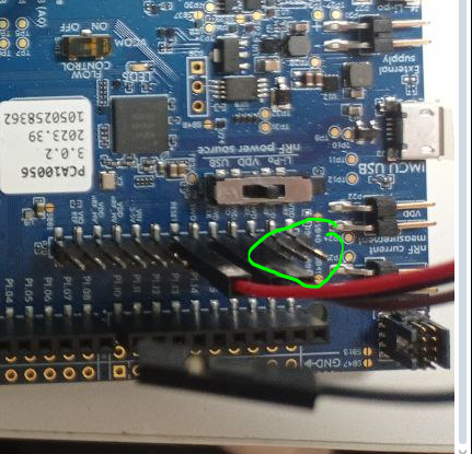
If I want to write this code to the nRF52840-DK - I just connect the DK via USB, then click "Build and run" - and it works. But I don't understand what I need to do to write the same code on my PCB board (not DK). On my PCB I have a SWD interface and a USB output, here is a photo:
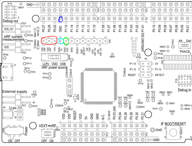
I soldered the wires to the SWD and then connected them to the DK. It's exactly like the picture below, except VDD. Instead, I connected the PCB itself via USB too, so that there was power.

After that I connected the DK to the computer via USB. I launched J-Flash, selected "Create a new project", indicated the board type "Noridc-Semi nrf52840" and selected the .hex file of my project (from the folder "ses\Output\Debug\Exe\"), pressed the F4 and F5 buttons - and it wrote “Target programmed successfully”, but nothing happened. The LED built into the PCB did not start blinking.
Hence my questions:
1) Please tell me how to use nRF52840-DK as a programmer, like J-Link? There may be some instructions that I haven't found.
2) How can I be sure that I have connected the SWD interface pins correctly? On a regular J-Link, the green LED should be lit, indicating that the device is connected via SWD. I read this somewhere, but I could be wrong...
Is there something similar in the nRF52840-DK? Or can I somehow see on the computer that I have a device connected via SWD?
3) Is this the correct sequence to load the program I need onto my PCB? I mean through a .hex file. Or should we do something differently?
Thank you in advance for your answers.