Hello,
I am programming BLE with the nRF52840-DK. [Toolchain Manager: v1.3.0, IDE: Visual Studio Code (VSCode), SDK: ncs v2.6.0, window11 pro]
< Simple Code Explanation >
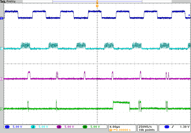
1. The ADC (SLAVE) and nRF52840 DK (MASTER) communicate via SPIM.
2. A command is sent to the ADC at regular intervals defined by 'TIME_TO_WAIT_US'.
- The TIMER is used to measure the intervals and PPI is used to start SPIM.
- The command buffer includes
tx_buf_arrayandtx_buf_array_2. (nRF52840 DK -> ADC) tx_buf_arrayis a command for ADC initialization.tx_buf_array_2is a command to retrieve ADC data and is intended to be sent repeatedly.- The SPIM handler exists to modify
Tx_PTRand to signal the end of SPIM. - The TIMER handler exists to signal the end of the TIMER.
< my issue>
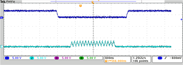
If TIME_TO_WAIT_US is less than 10, SPIM communication does not work properly. (ADC spec: Maximum SCLK frequency is 25 MHz)
I think a lot of time is being consumed in the handler. I'm not sure exactly what the problem is.
I want SPIM to work properly when 'TIME_TO_WAIT_US' is 5~6.
Could you give me some advice?
- Below is my code for the handler part:void spim1_handler(nrfx_spim_evt_t const * p_event, void * p_context) {
//LOG_INF("spim1_handler[%d] - TXD.PTR: 0x%08X", spi_counter, spim1_inst.p_reg->TXD.PTR);
if(spim1_inst.p_reg->TXD.PTR == (uint32_t)&tx_buf_array_2[17] + 2) {
spim1_inst.p_reg->TXD.PTR = (uint32_t)tx_buf_array_2[0];
} else if(spim1_inst.p_reg->TXD.PTR == (uint32_t)&tx_buf_array[30] ) {
spim1_inst.p_reg->TXD.PTR = (uint32_t)tx_buf_array_2[0];
}
if(spi_counter == MAX_SPI_COUNT){
spi_disable(spim1_inst.p_reg);
k_sem_give(&sem_condition1);
}
spi_counter++;
}
void timer0_handler(nrf_timer_event_t event_type, void * p_context){
if(spi_counter == MAX_SPI_COUNT){
timer_disable(&timer0_inst);
k_sem_give(&sem_condition2);
}
}
- Below is my code for the ppi part:
    /*   PPI  Setting  */
    uint32_t gpiote_task_addr = nrfx_gpiote_out_task_address_get(&gpiote_inst ,SS_PIN_MASTER);
    uint32_t timer_start_compare_event_addr = nrfx_timer_compare_event_address_get(&timer0_inst, NRF_TIMER_CC_CHANNEL0);
    uint32_t spi_start_task_addr   = nrfx_spim_start_task_address_get(&spim1_inst);
    uint32_t spi_end_evt_addr = nrfx_spim_end_event_address_get(&spim1_inst);

    // Timer reaches the desired tick -> GPIOTE toggle(off), SPI start
    error = nrfx_gppi_channel_alloc(&ppi_channel_spi_start);
    nrfx_gppi_channel_endpoints_setup(ppi_channel_spi_start, timer_start_compare_event_addr, gpiote_task_addr);
    nrfx_gppi_fork_endpoint_setup(ppi_channel_spi_start, spi_start_task_addr);

    // SPI tx-rx transmission ends -> GPIOTE toggle(on)
    error = nrfx_gppi_channel_alloc(&ppi_channel_spi_end);
    nrfx_gppi_channel_endpoints_setup(ppi_channel_spi_end, spi_end_evt_addr, gpiote_task_addr);