nRF52833-DK uart communication with nRF52840-DK

Hi,

I use two nRF52833-DK boards for uart communication (both using pin p0.06 for TX and p0.08 for RX),
with their TX and RX and GND pins connected to each other, and perform a UART transmission test:

One board is responsible for sending UART data, and the other board is responsible for receiving the data, the transmission works without any issues.

However, when I replace the receiving nRF52833-DK board with an nRF52840-DK board,
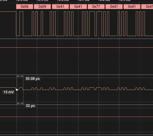
I find that when the UART RX pin on the nRF52840-DK receives UART data from the nRF52833-DK and the data is bit1,
the voltage level is about 3V, which is similar to the nRF52833-DK.
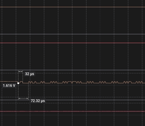
But when the data is bit0, the voltage level is raised to around 1.6V and cannot drop close to 0V, causing transmission problems.

Does the nRF52840-DK require any additional configuration to work with UART communication from the nRF52833-DK?
All DK boards are powered by VDD.

Parents
  • Tx and Rx are connected to the interface MCU (ATSAM) and need to be released to use externally. Try switch SW6, this switch controls this  /IF_OFF interface selection.

  • Released to use externally ??

    When connecting two nRF52833-DK boards together via UART,
    with one board sending and the other receiving, the signals are normal,
    and the receiving board is able to receive UART data from the sending board
    (without specifically switching SW6, keeping it at default).

    My question is: Why does the logic-0 signal of UART get pulled up to approximately 1.6V when the receiving board is changed from nRF52833-DK to nRF52840-DK?


    The following shows two nRF52833-DK boards connected together.
    When measuring the UART RX signal on the receiving nRF52833-DK board, the logic-0 voltage is almost 0V, and communication works properly.


    The following shows one nRF52833-DK and one nRF52840-DK boards connected together.
    the logic-0 voltage is approximately 1.6V.

  • Hi,

    Quick test to check if this is related to the new interface chip on the nRF52840 DKs is to repeat the test but with different GPIOs, can you change GPIOs from P0.06 and P0.08 and see if it's still an issue?

    regards
    Jared 

  • It is simple bus contention, maybe I wasn't clear: the nRF52840DK has an interface MCU (the debug interface) which is connected to P0.06 and P0.05. The IMCU is driving Tx at the same time the nRF52833 DK is driving Tx, both connected to the nRF52 Rx so when one drives high and the other drives low they fight and the voltage sits mid-rail or thereabouts.

    SW6 on the nRF52840DK disconnects the unwanted IMCU Tx

  • Thanks for sharing this information.
    Today, I tried to connect the usb cable to nRF52840 USB connector instead of IMCU USB connector, and the communication is normal. I didn't see the voltage being pull-up.


    I have following quesitons, that I would like to ask you because I switch the SW6 from DEFAULT to nRF ONLY on nRF52840-DK, and the 52840 doesn't seem to boot up.
    (when the application firmware runs, it should light up LED1, but I don't see LED1 turning on).

    I tried connecting the USB cable from the IWCU USB connector to the nRF52840 USB connector,
    but the situation remains the same.


    1. If I switch SW6 from DEFAULT to RF ONLY for this issue,  
    Do I need to make any additional adjustments?

    2. Additionaly, we still need to using JINK to debug and see the RTT conlose output,
    Does the setting still work? or I have to use other GPIO pin ?
    (To avoid issues arising from UART and the debug interface sharing the same pins

    3. Is the reason why the 52833 does not have this issue because it does not use P0.06 and P0.08 for the debug interface?"

  • The problem trying to use P0.05 and P0.06 on the nRF52840DK is that they are really not available as they are dedicated uart to IMCU and thence USB to PC. Yes SW6 isolates them, but then as you note the JLINK is also disabled.

    You could cut SB52 and SB53 (actually just SB52) but then you would lose serial connection via USB to PC. A better solution is to simply use two other pins on the nRF52840DK for Tx and Rx as jared suggested

Reply
  • The problem trying to use P0.05 and P0.06 on the nRF52840DK is that they are really not available as they are dedicated uart to IMCU and thence USB to PC. Yes SW6 isolates them, but then as you note the JLINK is also disabled.

    You could cut SB52 and SB53 (actually just SB52) but then you would lose serial connection via USB to PC. A better solution is to simply use two other pins on the nRF52840DK for Tx and Rx as jared suggested

Children
Related