Manual reflash of nRF 52840 Dongle - Failed to power up DAP

I'm trying to reflash the dongle with the "connectivity firmware". I previously used nRF Connect to do that, but with the latest version, the bootloader got somehow corrupted (it proposed to update the bootloader, i clicked no, then the device was no longer visible in Windows). The device is not even shown in device manager, so i suppose that the bootloader is somehow corrupted, and the USB connectivity is completly broken.

So instead of USB SDFU, i'm using a Jlink probe to reflash through SWD. 

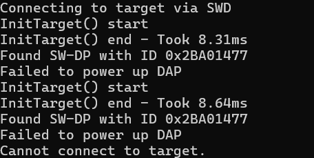
The following error message appears : 

CLCK, IO, Vtref and GND are cabled.

Best regards,

Parents Reply
  • Hi,

    Thank you. I upload the file here for reference: 31364.log.log (you can also upload fiels by drag-and-drop or by selecting Insert -> Image/video/file.

    The log shows that the debugger is not able to communicate with the nRF for some reason. Have you verified that it use 1.8V signals? Also, can you verify the connections? If there are still problems, you could try to lower the SWD frequency by using the clockspeed option with nrfjprog (for instance --clockspeed 500 to use 500 kHz) and see if that makes a difference.

Children
  • Hi Einar,

    Yes it uses 1.8V. I see it on the pin output of the J-Trace PRO. Decreasing SWD frequency to 1 kHz does nothing. 

    For reference, these pins are connected on the J-Trace : 

    VTref on VDD OUT

    SWDIO on SWDIO

    SWCLK on SWCLCK

    GND on GND

    From times to times i try to connect the RESET pin on the reset pin located in the P1 Pad below (this is the only reset pin, right ?) but it changes nothing.

  • Hi,

    The reset pin is available on the P1 pad (and the SW1 button). You do not need a reset pin in order to program or debug, though.

    Can you double check and show which pins you are using on the dongle as well and double check that you are using the correct ones (I would suggest soldering on a pin header on P1)?

  • Hi Einar,

    Sorry for the delay. 

    I just realized that I got timeout error "could not connect to target" with J-Link PRO and not with the J-Link EDU (I tried to flash other chip which worked previously and got timeout error with PRO model)

    So I may have an issue with t he J-Link PRO on my computer but that's weird, i need to investigate.

  • I see. If you are not able to get the J-Link PRO working, and alternative could be to power the dongle with 3V as explained under External regulated source, and use the J-Link EDU you have which is working.

  • What I don't understand is that according to the J-Link EDU datasheet https://www.segger.com/products/debug-probes/j-link/models/j-link-edu/ : 

    Target interface voltage (VIF)

    1.2V ... 5V

    So it should work with the default 1.8V. And I verified it, because i saw the RST Pin on the J-Link EDU at 1.8V (Always HIGH until a RST is needed then it is pulled down, right ?). In this case, why the PRO is needed ?