TXB0108PWR Voltage Level Translator + nrf52840dk + SPI issues

Hi, 

We built a nrf52840dk shield that interfaces with an SPI sensor connecting to GPIO_IF4. We require using a voltage translator to translate 3.3V signals into 5V to comunicate with the sensor, because of the rest of our design requires using this 5v source.

We are setting the output voltage from REG0 regulator stage to 3.3V. Somehow the voltage translator is messing up the SPI communication. If we remove the voltage translator the SPI communication at 3v (the sensor also supports it, even though we cannot use it in our design), it works as expected.

Also, we tested using an ESP32-S3 dev board with the same shield to comunnicate with the SPI slave/sensor and the communication worked correctly.

Also, we cut the solder bridges SB10...SPB15 and soldered SB20...SB25 so we do not use the qspi external flash memory.

Looking at the schematic do you see any reason why this specific voltage translator wouldn't work with the DK for SPI signals, but works with ESP32 just fine ?

Follows in attachment the altium files of our shield.
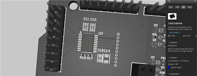
Thanks in advance for any support.

Best regards,
Pedro Machado

Parents
  • Hi

    The schematics looks okay to me, and I can't say I see why this should cause trouble for the SPI communication. Are you able to probe the data lines to see what's happening on the lines themselves with a logic analyzer?

    On the DK, what states are the switches set to here? As the power source for example should be set to Li-Po if you power it on P27 for example.

    Best regards,

    Simon

Reply
  • Hi

    The schematics looks okay to me, and I can't say I see why this should cause trouble for the SPI communication. Are you able to probe the data lines to see what's happening on the lines themselves with a logic analyzer?

    On the DK, what states are the switches set to here? As the power source for example should be set to Li-Po if you power it on P27 for example.

    Best regards,

    Simon

Children
  • Hi Simon,

    Probing the lines with a logic analyser didn't quite clear thing up. Everything looked as expected but the client devices' response didn't make much sense. We only got the expected response around 20% of the time.

    However, we did manage to solve the issue. Using an oscilloscope, we saw a lot of ringing/reflections in pretty much every edge of every signal on the high voltage side of the voltage translator, as well as some cross talk from CLK into MISO and CS. The logic analyser wasn't catching the cross-talk and the ringing (glitch filter was on).

    The TXB0108 seems to be particularly sensitive to either reflections, capacitive loads, cross-talk or cables with higher impedance. What eventually solved our issue was to shorten the cable connecting the high voltage side of the TXB0108 to the sensor from 50cm to 40cm, twisting the signal wires with GND and VCC (CLK with GND, MISO with VCC, MOSI with VCC, etc), and shielding the cable with copper tape. With this new cable, everything started working as expected with no ringing (perhaps the edge-rate accelerator was being triggered by it).

    Ideally we would have just bypassed the cable and shortened the connection as much as possible, but the sensor we are using doesn't allow for that. We are stuck with using a cable for SPI communication with this specific sensor.

    During our testing, we also found out that the TXS0108E worked flawlessly while using the longer unshielded cable. It seems to us that this voltage translator is a lot more forgiving than the TXB0108.

    Moving forward, we will swap to the TXS0108E and a properly twisted/shielded slightly shorter cable.

    On a side note, we didn't do any follow up to the OE signal suggestion. Keeping it tied high doesn't seem to be affecting our sensor.

    Thank you all for your feedback!

Related