We have developed a custom board based on the nRF52840-CKAA-R7.
Development is well into the re-release phase, and I am having some issues with battery life.
I've done significant testing and have isolated found a number of issues that I don't understand.
To demonstrate the issues I've put together five example VScode projects, which are included in the attached zip file.
The first issue has to do with the uart and is demonstrated by example_1 and example_2.
These two projects are truly bare-bones - prj.conf is empty, app.overlay has at most one entry and main.c is very short with only 31 lines of code.
The only difference between the two projects is in app.overlay.
In example_1, app.overlay has uart0 disabled. In example_2, app.overlay is empty.
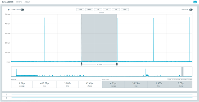
Measuring battery current draw with a DVM I see that example_1 draws 10 micro-amps, with a spike every two seconds when the timer interrupt occurs.
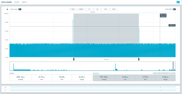
The same measurement in example_2 shows 3.3 milli-Amps (3300 micro-Amps).
I simply don't understand why this is happening.
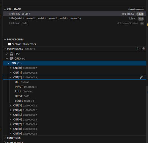
The second issue has to do with gpio tailoring and is demonstrated by example_3 and example_4.
These projects incorporate code from my production environment - a module named gpio.c and an include file (common.h) that contains among other things gpio pin definitions.
In example_3 includes nearly all of my production gpio port tailoring.
In example_4 I have commented out the code that initializes all input ports.
Measuring battery current in example_3 shows 32 micro-Amps with a spike every two seconds when the timer interrupt occurs.
The same measurement in example_4 shows 10 micro-amps, with a spike every two seconds when the timer interrupt occurs - the same pattern I see in example_1.
I don't understand why tailoring gpio ports impacts current draw.
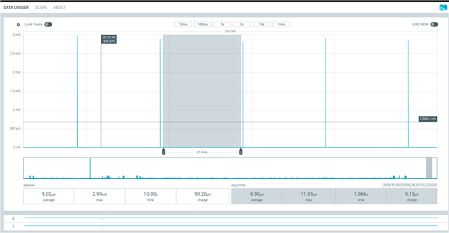
The third issue has to do with I2S and is demonstrated by example_5.
This project - built on top of example_4 - includes production code for I2S.
Measuring battery current the same way as I did before, example_5 shows current draw of about 10 micro_amps when the board is powered up. Current slowly increases, reaching 330 micro-Amps in about thirty seconds, then suddenly drops and stabilizes at 230 micr0-Amps.
Note that the I2S chip I'm communicating with is not powered up.
ALso note that I've tried to use power management on the I2S port. When I try to suspend the device, Zephyr returns a -88 - Feature not supported.
A few additional notes.
Each project has a custom board in the boards directory.