Adding additional channels to FDC2X1X sample code on nRF9160 DK

Hello,

I have gotten the Zephyr FDC2X1X sample code running with a single FDC2214 I2C capacitive sensor sampling two out of the four channels. The device tree for this configuration is such:

&i2c2 {
	clock-frequency = <I2C_BITRATE_FAST>;
	fdc2x1x@2A {
		compatible = "ti,fdc2x1x";
		reg = <0x2A>;
		sd-gpios = <&gpio0 16 GPIO_ACTIVE_HIGH>;
		intb-gpios = <&gpio0 20 GPIO_ACTIVE_LOW>;

		autoscan;
		deglitch = <5>;
		fref = <43360>;

		channel_0 {
			rcount = <7499>;
			settlecount = <48>;
			fref-divider = <1>;
			idrive = <10>;
			fin-sel = <2>;
			inductance = < 18 >;
		};

		channel_1 {
			rcount = <7499>;
			settlecount = <48>;
			fref-divider = <1>;
			idrive = <10>;
			fin-sel = <2>;
			inductance = <18>;
		};
	};
};

I would like to read the other two channels of the sensor aka channel 2 & 3. The sample documentation says that this is controlled via the device tree. So I updated the device tree as such: 

&i2c2 {
	clock-frequency = <I2C_BITRATE_FAST>;
	fdc2x1x@2A {
		compatible = "ti,fdc2x1x";
		reg = <0x2A>;
		sd-gpios = <&gpio0 16 GPIO_ACTIVE_HIGH>;
		intb-gpios = <&gpio0 20 GPIO_ACTIVE_LOW>;

		
		autoscan;
		deglitch = <5>;
		fref = <43360>;

		channel_0 {
			rcount = <7499>;
			settlecount = <48>;
			fref-divider = <1>;
			idrive = <10>;
			fin-sel = <2>;
			inductance = < 18 >;
		};

		channel_1 {
			rcount = <7499>;
			settlecount = <48>;
			fref-divider = <1>;
			idrive = <10>;
			fin-sel = <2>;
			inductance = <18>;
		};

		channel_2 {
			rcount = <7499>;
			settlecount = <48>;
			fref-divider = <1>;
			idrive = <10>;
			fin-sel = <2>;
			inductance = <18>;
		};

		channel_3 {
			rcount = <7499>;
			settlecount = <48>;
			fref-divider = <1>;
			idrive = <10>;
			fin-sel = <2>;
			inductance = <18>;
		};


		fdc2x14;
	};
};

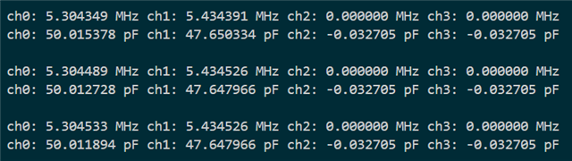
to include the additional two channels, and added the fdc2x14; identifier to signify that the FDC2214 4-channel device is connected. When I recompile the sample I see four channel outputs on the serial console, but the second and third channel display fixed out of range values, like those channels are not configured properly.

Any ideas on how to get this working?

Cheers,

Parker

Parents
  • Hi Parker,

    I do not have experience with the sensor, and this driver was not worked on by Nordic. However, I see that in addition to the example documentation describing just channels you also need to set the fdc2x14 in your device tree overlay, which you have.

    Do you see anything interesting from debugging? Also, are you able to use one of the last two channels if you specify a specific channel using the active-channel property instaed of autocan?

    Einar

  • Hi Einar,

    I have started setting breakpoint and debugging the driver. I can see the driver is correctly calling static int fdc2x1x_init_config(const struct device *dev) and looping through all four channels. Likewise, when it goes to read channels, it correctly loops through all four channels one at a time. I probed each of the fdc2214 channel outputs on the circuit board and only channel 0/1 are actually generating an output signal. My current hypothesis is the initialization function is somehow not enabling these channels correctly and that is why the readout comes back with an out of range result (as opposed to there being an issue with the readout function). I will try using the active-channel property instead of autoscan when I get to the lab this morning, but I suspect the issue is with initialization not the readout mode. But who knows!

    Cheers,

    Parker

  • Also I have verified that this is a software issue as I can use Ti's firmware to read all four channels in autoscan mode via their development kit.

  • Figured it out. Turns out the driver correctly puts the FDC2214 in autoscanning mode (aka device automatically samples and converts channels), but it doesn't update the RR_SEQUENCE[14:13] correctly. By default it sets RR_SEQUENCE to 0b00 which only enables channels 0 & 1 to be converter. By setting RR_SEQUENCE to 0b10 (as shown in the datasheet) all four channels get read out correctly. 

    This can be achieved by settings rr-sequence = <2>; in the devicetree. More devicetree options are shown in ti,fdc2x1x.yaml.

    Cheers,

    Parker

Reply
  • Figured it out. Turns out the driver correctly puts the FDC2214 in autoscanning mode (aka device automatically samples and converts channels), but it doesn't update the RR_SEQUENCE[14:13] correctly. By default it sets RR_SEQUENCE to 0b00 which only enables channels 0 & 1 to be converter. By setting RR_SEQUENCE to 0b10 (as shown in the datasheet) all four channels get read out correctly. 

    This can be achieved by settings rr-sequence = <2>; in the devicetree. More devicetree options are shown in ti,fdc2x1x.yaml.

    Cheers,

    Parker

Children
No Data
Related