DevAcademy Intermediate Lesson 5 Exercise 2 with Elegoo 2.8" TFT screen

I'm trying to follow the DevAcademy Intermediate Lesson 5 Exercise 2 using an Elegoo shield instead of the Adafruit one.

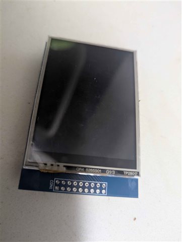
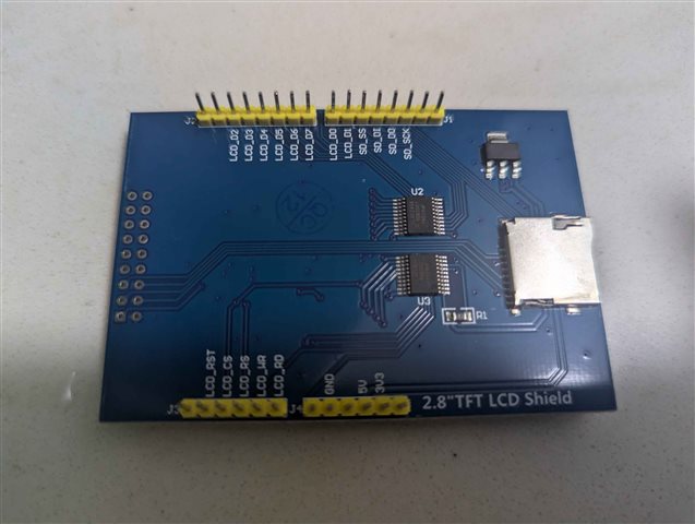
The shield I'm using is this one: https://www.elegoo.com/blogs/arduino-projects/elegoo-2-8-inch-touch-screen-for-raspberry-pi-manual

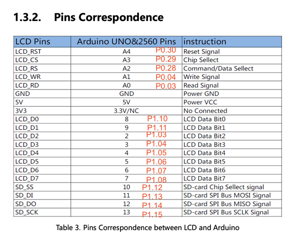
It also uses the same controller (ILI9341) and as far as I can tell, the pins are the same (see attached screenshot). However, all I'm getting is a white screen.

There's nothing unusual in the logs:

*** Booting nRF Connect SDK v3.5.99-ncs1 ***
[00:00:00.378,326] <inf> Lesson5_Exercise2: Display Sample on ili9340@0: Orientation=1,  Pixel-format=1,   X-res=320,   Y-res=240
[00:00:00.675,476] <inf> Lesson5_Exercise2: Displaying diagonal line, starting pixel (x, y) = 20, 20
[00:00:02.716,857] <inf> Lesson5_Exercise2: Last pixel (x, y)= 120, 120
[00:00:02.716,918] <inf> Lesson5_Exercise2: Displaying series of lines (1 line at a time), starting line (x, y) = 100, 100
[00:00:03.244,873] <inf> Lesson5_Exercise2: Last line (x, y)= 100, 25
[00:00:03.245,452] <inf> Lesson5_Exercise2: Displaying a rectangular box, top left corner (x,y) = 30, 130
[00:00:03.255,218] <inf> Lesson5_Exercise2: Bottom right corner (x, y) of box = 110, 170

Using nrf v2.6.0.

Any idea what's wrong?

  • After further inspection, it looks like the pins were not exactly the same, so I modified the overlay (boards/nrf52840dk_nrf52840.overlay) as follows:

    &spi3{
        compatible = "nordic,nrf-spim";
        #address-cells = < 0x1 >;
        #size-cells = < 0x0 >;
        reg = < 0x4002f000 0x1000 >;
        interrupts = < 0x2f 0x1 >;
        max-frequency = < 0x1e84800 >;
        easydma-maxcnt-bits = < 0x10 >;
        rx-delay-supported;
        rx-delay = < 0x2 >;
        status = "okay";
        //  p0.29 (A3), p1.12 (D10)
        cs-gpios = < &arduino_header 0x3 0x1 >, < &arduino_header 0x10 0x1 >;
        pinctrl-0 = < &spi3_default >;
        pinctrl-1 = < &spi3_sleep >;
        pinctrl-names = "default", "sleep";
        ili9340: ili9340@0 {
            compatible = "ilitek,ili9340";
            spi-max-frequency = < 0xe7319b >;
            reg = < 0x0 >;
            // p0.28 (A2)
            cmd-data-gpios = < &arduino_header 0x2 0x1 >;
            width = < 0x140 >;
            height = < 0xf0 >;
            pixel-format = < 0x1 >;
            rotation = < 0x5a >;
            frmctr1 = [ 00 18 ];
            pwctrl1 = [ 23 00 ];
            vmctrl1 = [ 3E 28 ];
            vmctrl2 = [ 86 ];
            pgamctrl = [ 0F 31 2B 0C 0E 08 4E F1 37 07 10 03 0E 09 00 ];
            ngamctrl = [ 00 0E 14 03 11 07 31 C1 48 08 0F 0C 31 36 0F ];
        };
        adafruit_2_8_tft_touch_v2_sdhc: sdhc@1 {
            compatible = "zephyr,sdhc-spi-slot";
            reg = < 0x1 >;
            status = "okay";
            spi-max-frequency = < 0x16e3600 >;
            mmc {
                compatible = "zephyr,sdmmc-disk";
                status = "okay";
            };
        };
    };
    
    &pinctrl {
        spi3_default{
            group1 {
                    psels = <NRF_PSEL(SPIM_SCK, 1, 15)>,
                            <NRF_PSEL(SPIM_MISO, 1, 14)>,
                            <NRF_PSEL(SPIM_MOSI, 1, 13)>;
            };
        };
    
        spi3_sleep{
            group1 {
                    psels = <NRF_PSEL(SPIM_SCK, 1, 15)>,
                            <NRF_PSEL(SPIM_MISO, 1, 14)>,
                            <NRF_PSEL(SPIM_MOSI, 1, 13)>;
                    low-power-enable;
            };
        };
    };

    Modified lines:

        //  p0.29 (A3), p1.12 (D10)
        cs-gpios = < &arduino_header 0x3 0x1 >, < &arduino_header 0x10 0x1 >;
        
        // p0.28 (A2)
        cmd-data-gpios = < &arduino_header 0x2 0x1 >;

    But still a blank screen. I noticed from the board's docs that the SPI pins appear to be for the SD card only... Maybe why it's not working?

  • Hi,

    It looks like your SPI configuration is for the SD card SPI, yes, and not for communicating with the LCD display.

    The shield used on DevAcademy supports the "4-wire 8-bit data serial interface II" MCU interface, which is also what is used for the exercise. The Elegoo board, on the other hand, doesn't support this mode, but rather uses the "8080 MCU 8-bit bus interface" mode.

    This means, in short, that the shield that you are using is not compatible with the DevAcademy exercise.

    In order to use the Elegoo shield, you would need the proper set of drivers for using the bus interface (instead of using SPI), as well as the correct overlay configuration for setting up the pins of the bus interface for that bus driver.

    Regards,
    Terje

Related