PPK2 software update 4.2.0 produces vastly differing current readings to previous software releases.

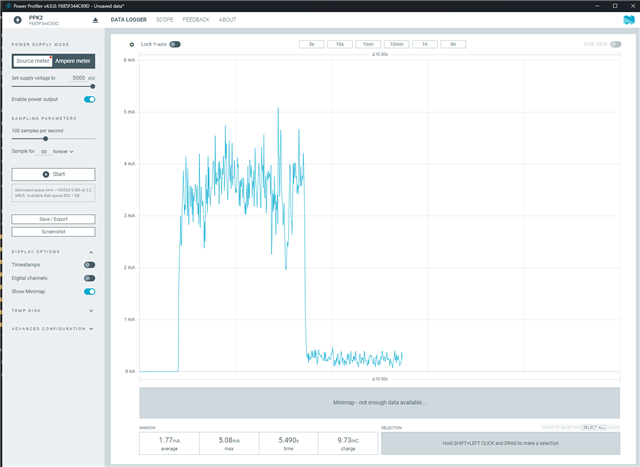
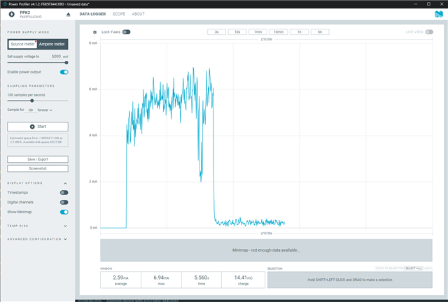
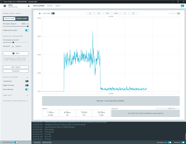
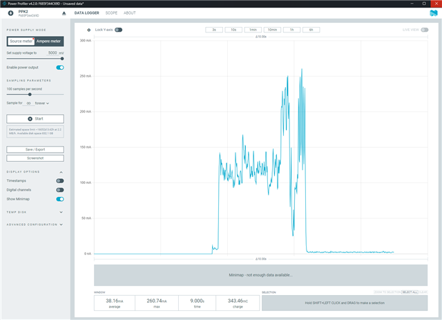
Below are power consumption measurements of a DUT being booted with the same PPK2 in SMU mode with various software versions. The only variable being changed is the PPK2 software version.

V4.0.0, V4.1.2, V4.1.3 all show peak around 5mA

V4.2.0 shows a peak of around 250mA, and a completely different profile.

PPK2 s/n  F685F344C69D

 4.1.24.1.34.2.0

Parents
  • Hi ,

    this release includes changes to the ADC sampling. Specifically how the firmware determines if a sample is valid (it is not valid if a measurement range transition has happened at the same time as the ADC measurement).

    During testing it was observed that some DUTs had behavior similar to what you see. Specifically, the old firmware showed lower peaks and lower averages than the new firmware. The new firmware had some peaks not observed with a reference instrument, but the average measured current with the new firmware was closer to the reference.

    In general, the PPK2 measurements can become inaccurate for loads that hover around the edges of measurement ranges.

    What is the expected peak and average current consumption for your device? I assume the measurements using the new firmware is not what you expect, but I'd like to understand your load a bit better. For example, which part is the primary consumer of power on your design, and what is the expected peak current from that.

    The new firmware adds a secondary COM port for shell access debugging purposes. You can get some more information using the nRF Connect Serial Terminal app:

    In the "Serial port" drop down menu, there should be 2 x ports. Use the one not already in use by Power Profiler.

    Also note that the shell is not responsive while the PPK2 is sampling. Execute the "sampling metrics" shell command after you've stopped sampling.

    If the "Samples dropped" value is high, it would indicate that your DUT has a power profile that PPK2 struggles with.

    Best regards,

    Audun

  • Hi Audun, 

    Thanks for the comprehensive response. 

    v4.2.0

    Your thinking was correct, lots of dropped samples.

    If I put my handheld MM in series to take mA readings, standby current shows as ~0.760mA, PPK2 shows 1-1.4mA, they both agree on a peak of around 10-20mA.

    If I take my MM out of the system then I see a very different profile (similar to my OP), with peaks in hundreds of mA and standby current around 2.5mA.

    Attached:

    - serial results both with and without MM showing many dropped samples

    - ppk2 files showing boot with and without MM(shunt) in place.

    - log file with mm

    - system diag file

    v4.1.3

    Same results as my OP, same with and without the multimeter. 

     MM still suggesting ~0.760mA, PPK2 estimate is 0.247mA.

    Attached:

    -ppk2 with and without mm 

    - log file no mm

    (I can DM the schematic over to you if it helps, but it's nothing special, just a fairly normal Power supply / MCU / RS485 transceiver type arrangement)

    I have a Keithley DMM6500 available next week, I can use that as a reference. 

    ver413vs420.zip

Reply
  • Hi Audun, 

    Thanks for the comprehensive response. 

    v4.2.0

    Your thinking was correct, lots of dropped samples.

    If I put my handheld MM in series to take mA readings, standby current shows as ~0.760mA, PPK2 shows 1-1.4mA, they both agree on a peak of around 10-20mA.

    If I take my MM out of the system then I see a very different profile (similar to my OP), with peaks in hundreds of mA and standby current around 2.5mA.

    Attached:

    - serial results both with and without MM showing many dropped samples

    - ppk2 files showing boot with and without MM(shunt) in place.

    - log file with mm

    - system diag file

    v4.1.3

    Same results as my OP, same with and without the multimeter. 

     MM still suggesting ~0.760mA, PPK2 estimate is 0.247mA.

    Attached:

    -ppk2 with and without mm 

    - log file no mm

    (I can DM the schematic over to you if it helps, but it's nothing special, just a fairly normal Power supply / MCU / RS485 transceiver type arrangement)

    I have a Keithley DMM6500 available next week, I can use that as a reference. 

    ver413vs420.zip

Children
Related