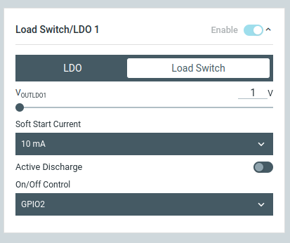
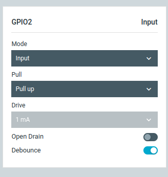
How to set an interrupt on LDSW via GPIO in the NPM1300 using the nRF Connect SDK.

I am using NCS v2.5.1 and working on a project where I need to turn off the system using a button that triggers an interrupt on a GPIO. I want this GPIO to control a load switch to turn it on and off. Where both the GPIO and the load switch are part of the NPM1300. How can I achieve this using the nRF Connect SDK?

Is there any configuration available in overlay file? 

Parents
  • Hi Priyesh,

    I will make a new conversation thread here, to start anew.
    First, I recommend that you test with the nPM PowerUp application to get the functionality you need.

    I tried this now, and think I got what you want.
    Can you watch the video below, and confirm if this is what you need?

    Then you can use the "export" feature in nPM PowerUp to get the DTS configuration you need.

    Here are the options I used:

  • Yes, this is exactly what I want to do. I tried this with the nPM PowerUp application and the nPM1300EK board, and everything you suggested is working perfectly on that.

    However, when I export the configuration and add it to my project, it doesn't seem to work. Could you provide me with a sample or some guidance on how to make it work in my project? That would be really helpful.

    Thank you!

Reply Children
  • Priyesh Shahi said:
    However, when I export the configuration and add it to my project, it doesn't seem to work. Could you provide me with a sample or some guidance on how to make it work in my project? That would be really helpful.

    Have you been able to apply any other configurations from the nPM Power Up application to a DK successfully?
    It would be good to know if it is an issue with this specific feature, or with your nPM config in general.

    After we find out this, I can try to reproduce it at my end

  • Yes, Earlier in my project, I set the nPM regulator in AUTO mode using the following lines:

    regulator-allowed-modes = <NPM1300_BUCK_MODE_AUTO>;
    regulator-initial-mode = <NPM1300_BUCK_MODE_AUTO>;

    I also deleted the PWM properties from Buck 2 using the following lines:

    /delete-property/ retention-gpios;
    /delete-property/ pwm-gpios;

    I also set the Buck 1 voltage to 3.3V using this line:

    regulator-init-microvolt = <3300000>;

    Additionally, I made other changes in the charger device, such as setting the charging current and maximum voltage, and those configurations are working.

    Here is the config file I used in my project:

    /*
     * Copyright (C) 2023 Nordic Semiconductor ASA
     * SPDX-License-Identifier: Apache-2.0
     */
    
    #include <dt-bindings/regulator/npm1300.h>
    #include <zephyr/dt-bindings/input/input-event-codes.h>
    #define NPM1300_BUCK_MODE_PFM 0x04U
    
    &arduino_i2c {
    	npm1300_ek_pmic: pmic@6b {
    		compatible = "nordic,npm1300";
    		reg = <0x6b>;
    
    		npm1300_ek_gpio: gpio-controller {
    			compatible = "nordic,npm1300-gpio";
    			gpio-controller;
    			#gpio-cells = <2>;
    			ngpios = <5>;
    		};
    
    		npm1300_ek_regulators: regulators {
    			compatible = "nordic,npm1300-regulator";
    
    			npm1300_ek_buck1: BUCK1 {
    				regulator-min-microvolt = <1000000>;
    				regulator-max-microvolt = <3300000>;
    				regulator-init-microvolt = <3300000>;
    				retention-microvolt = <2500000>;
    				regulator-allowed-modes = <NPM1300_BUCK_MODE_AUTO>;
    				regulator-initial-mode = <NPM1300_BUCK_MODE_AUTO>;
    			};


    			npm1300_ek_buck2: BUCK2 {
    				regulator-min-microvolt = <1000000>;
    				regulator-max-microvolt = <3300000>;
    				/delete-property/ regulator-init-microvolt;
    				retention-microvolt = <2500000>;
    				regulator-allowed-modes = <NPM1300_BUCK_MODE_AUTO>;
    				regulator-initial-mode = <NPM1300_BUCK_MODE_AUTO>;
    				enable-gpios = <&npm1300_ek_gpio 0 GPIO_ACTIVE_HIGH>;
    				/delete-property/ retention-gpios;
    				/delete-property/ pwm-gpios;
    			};


    			npm1300_ek_ldo1: LDO1 {
    				regulator-min-microvolt = <1000000>;
    				regulator-max-microvolt = <3300000>;
    				regulator-init-microvolt = <2500000>;
    				regulator-initial-mode = <NPM1300_LDSW_MODE_LDSW>;
    				// soft-start-microamp = <10000>;
    				enable-gpios = <&npm1300_ek_gpio 2 GPIO_ACTIVE_HIGH>;
    
    			};


    			npm1300_ek_ldo2: LDO2 {
    				regulator-min-microvolt = <1000000>;
    				regulator-max-microvolt = <3300000>;
    				regulator-init-microvolt = <2500000>;
    				regulator-initial-mode = <NPM1300_LDSW_MODE_LDO>;
    				// soft-start-microamp = <10000>;
    				enable-gpios = <&npm1300_ek_gpio 1 GPIO_ACTIVE_HIGH>;
    			};
    		};
    
    
    		npm1300_ek_charger: charger {
    			compatible = "nordic,npm1300-charger";
    			term-microvolt = <4200000>;
    			term-warm-microvolt = <3600000>;
    			// term-current-percent = <20>;
    			current-microamp = <800000>;
    			// trickle-microvolt = <2900000>;
    			dischg-limit-microamp = <1000000>;
    			vbus-limit-microamp = <1500000>;
    			thermistor-ohms = <10000>;
    			thermistor-beta = <3380>;
    		};
    
    		npm1300_ek_leds: leds {
    			compatible = "nordic,npm1300-led";
    			nordic,led0-mode = "charging";
    			nordic,led1-mode = "charging";
    			nordic,led2-mode = "charging";
    		};
    
    	};
    };

  • I have been able to reproduce the issue you have an have reported it to our devs as a potential bug.
    I will let you know as soon as they got some way to fix this (either by correcting our mistake or by finding the bug).

  • Hello, any update on this bug on the nPM1300 LDSW triggering.

  • The pin can be configured in the app. That should fix it:

    int err = gpio_pin_configure(pmic_gpio, 1, GPIO_INPUT | GPIO_ACTIVE_HIGH | GPIO_PULL_UP);
    if (err) {
      printk("gpio_pin_configure=%d\n", err);
    }

Related