Hi Nordic community,
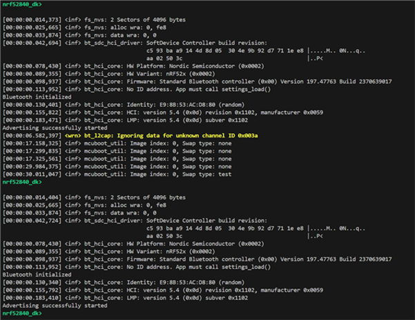
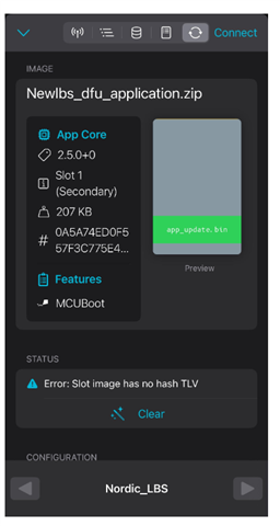
I'm currently working on a project where I'm aiming to implement FOTA updates on the nRF52840 DK, with the application images stored on the MX25R64 external flash.
To summarize: My application requires around 600KB of storage. When I enable CONFIG_MCUBOOT_BOOTLOADER, a significant portion of the 1MB internal flash is consumed, resulting in a flash overflow when attempting to flash the program.
I'm trying to expand the flash region to utilize the 64MB available on the MX25R64 external flash. However, I'm encountering difficulties with configuring the necessary config, yaml, and dts files.
From my research, it seems I need to use LittleFS to access the external flash over QSPI. I've attached my current prj.conf and related configuration files. I would greatly appreciate any guidance or example code that demonstrates how to perform FOTA updates using the external flash.
Thank you in advance for your help!
proj.conf:
# Deactivate DEBUG/LOG for production builds
# Logging
CONFIG_LOG=y

#### BLE ####
# Activate the BLE layer, set as peripheral
CONFIG_BT=y
CONFIG_BT_SMP=y
CONFIG_BT_PERIPHERAL=y
CONFIG_BT_CTLR=y
CONFIG_BT_CTLR_PHY_2M=y
CONFIG_BT_GATT_CLIENT=y
# Set up the Services
CONFIG_BT_DIS=y
CONFIG_BT_DIS_PNP=n

# Allow another device that unpaired to pair again
CONFIG_BT_SMP_ALLOW_UNAUTH_OVERWRITE=y

#### FLASH ####
# Configure stack size for process
CONFIG_MAIN_STACK_SIZE=8192
CONFIG_SYSTEM_WORKQUEUE_STACK_SIZE=8192

##### MCUBOOT #####
# Enable mcumgr. #Turn to y if BOOTLOADER
CONFIG_ZCBOR=y
CONFIG_MCUMGR=y
# Ensure an MCUboot-compatible binary is generated. MCUboot is the upgradable bootloader. #Turn to y if BOOTLOADER
CONFIG_BOOTLOADER_MCUBOOT=y
# Enable most core commands. #Turn to y if BOOTLOADER
##CONFIG_MCUMGR_CMD_IMG_MGMT=y
CONFIG_STREAM_FLASH=y
CONFIG_IMG_MANAGER=y
CONFIG_MCUMGR_GRP_IMG=y

##CONFIG_MCUMGR_CMD_OS_MGMT=y
CONFIG_MCUMGR_GRP_OS=y
# Enable the Bluetooth (unauthenticated) mcumgr transports. #Turn to y if BOOTLOADER
##CONFIG_MCUMGR_SMP_BT=y
CONFIG_MCUMGR_TRANSPORT_BT=y
##CONFIG_MCUMGR_SMP_BT_AUTHEN=n
CONFIG_MCUMGR_TRANSPORT_BT_AUTHEN=y
# Generate a confirmed image directly
CONFIG_MCUBOOT_GENERATE_CONFIRMED_IMAGE=y

# This value must match the size of the MCUboot primary partition
CONFIG_PM_EXTERNAL_FLASH_MCUBOOT_SECONDARY=y
#CONFIG_PM_PARTITION_SIZE_MCUBOOT_SECONDARY=0xe0000

# Enable flash operations
CONFIG_FLASH=y
CONFIG_FLASH_PAGE_LAYOUT=y

CONFIG_FLASH_MAP=y
CONFIG_MCUBOOT_IMG_MANAGER=y
#CONFIG_IMG_BLOCK_BUF_SIZE=512

#CONFIG_MULTITHREADING=y
CONFIG_TIMESLICING=y
CONFIG_THREAD_MONITOR=y

CONFIG_SPI=y
CONFIG_SPI_NOR=y
CONFIG_LOG_MODE_MINIMAL=y
CONFIG_MPU_ALLOW_FLASH_WRITE=y

CONFIG_FILE_SYSTEM=y
CONFIG_FILE_SYSTEM_LITTLEFS=y
CONFIG_SETTINGS=y

CONFIG_SETTINGS_FS=y

CONFIG_SPI_NOR_FLASH_LAYOUT_PAGE_SIZE=4096

CONFIG_LOG_MODE_IMMEDIATE=y

CONFIG_SETTINGS_FS_DIR="/lfs/settings"
CONFIG_SETTINGS_FS_FILE="/lfs/settings/run"

# Partition manager settings
CONFIG_PM_EXTERNAL_FLASH_MCUBOOT_SECONDARY=n
pm.static:
external_flash:
  address: 0x0
  end_address: 0x400000 # 64mb
  region: external_flash
  size: 0x400000
littlefs_storage:
  address: 0x0
  device: MX25R64_SPI
  region: external_flash
  size: 0x400000
nrf52840dk_nrf52840.dts
/*
 * Copyright (c) 2017 Linaro Limited
 *
 * SPDX-License-Identifier: Apache-2.0
 */

 /dts-v1/;
 #include <nordic/nrf52840_qiaa.dtsi>
 #include "nrf52840dk_nrf52840-pinctrl.dtsi"
 #include <zephyr/dt-bindings/input/input-event-codes.h>

 / {
     model = "Nordic nRF52840 DK NRF52840";
     compatible = "nordic,nrf52840-dk-nrf52840";

     chosen {
         zephyr,console = &uart0;
         zephyr,shell-uart = &uart0;
         zephyr,uart-mcumgr = &uart0;
         zephyr,bt-mon-uart = &uart0;
         zephyr,bt-c2h-uart = &uart0;
         zephyr,sram = &sram0;
         zephyr,flash = &flash0;
         zephyr,code-partition = &slot0_partition;
         zephyr,ieee802154 = &ieee802154;
     };

     leds {
         compatible = "gpio-leds";
         led0: led_0 {
             gpios = <&gpio0 13 GPIO_ACTIVE_LOW>;
             label = "Green LED 0";
         };
         led1: led_1 {
             gpios = <&gpio0 14 GPIO_ACTIVE_LOW>;
             label = "Green LED 1";
         };
         led2: led_2 {
             gpios = <&gpio0 15 GPIO_ACTIVE_LOW>;
             label = "Green LED 2";
         };
         led3: led_3 {
             gpios = <&gpio0 16 GPIO_ACTIVE_LOW>;
             label = "Green LED 3";
         };
     };

     pwmleds {
         compatible = "pwm-leds";
         pwm_led0: pwm_led_0 {
             pwms = <&pwm0 0 PWM_MSEC(20) PWM_POLARITY_INVERTED>;
         };
     };

     buttons {
         compatible = "gpio-keys";
         button0: button_0 {
             gpios = <&gpio0 11 (GPIO_PULL_UP | GPIO_ACTIVE_LOW)>;
             label = "Push button switch 0";
             zephyr,code = <INPUT_KEY_0>;
         };
         button1: button_1 {
             gpios = <&gpio0 12 (GPIO_PULL_UP | GPIO_ACTIVE_LOW)>;
             label = "Push button switch 1";
             zephyr,code = <INPUT_KEY_1>;
         };
         button2: button_2 {
             gpios = <&gpio0 24 (GPIO_PULL_UP | GPIO_ACTIVE_LOW)>;
             label = "Push button switch 2";
             zephyr,code = <INPUT_KEY_2>;
         };
         button3: button_3 {
             gpios = <&gpio0 25 (GPIO_PULL_UP | GPIO_ACTIVE_LOW)>;
             label = "Push button switch 3";
             zephyr,code = <INPUT_KEY_3>;
         };
     };

     arduino_header: connector {
         compatible = "arduino-header-r3";
         #gpio-cells = <2>;
         gpio-map-mask = <0xffffffff 0xffffffc0>;
         gpio-map-pass-thru = <0 0x3f>;
         gpio-map = <0 0 &gpio0 3 0>,   /* A0 */
                <1 0 &gpio0 4 0>,   /* A1 */
                <2 0 &gpio0 28 0>,  /* A2 */
                <3 0 &gpio0 29 0>,  /* A3 */
                <4 0 &gpio0 30 0>,  /* A4 */
                <5 0 &gpio0 31 0>,  /* A5 */
                <6 0 &gpio1 1 0>,   /* D0 */
                <7 0 &gpio1 2 0>,   /* D1 */
                <8 0 &gpio1 3 0>,   /* D2 */
                <9 0 &gpio1 4 0>,   /* D3 */
                <10 0 &gpio1 5 0>,  /* D4 */
                <11 0 &gpio1 6 0>,  /* D5 */
                <12 0 &gpio1 7 0>,  /* D6 */
                <13 0 &gpio1 8 0>,  /* D7 */
                <14 0 &gpio1 10 0>, /* D8 */
                <15 0 &gpio1 11 0>, /* D9 */
                <16 0 &gpio1 12 0>, /* D10 */
                <17 0 &gpio1 13 0>, /* D11 */
                <18 0 &gpio1 14 0>, /* D12 */
                <19 0 &gpio1 15 0>, /* D13 */
                <20 0 &gpio0 26 0>, /* D14 */
                <21 0 &gpio0 27 0>; /* D15 */
     };

     arduino_adc: analog-connector {
         compatible = "arduino,uno-adc";
         #io-channel-cells = <1>;
         io-channel-map = <0 &adc 1>,   /* A0 = P0.3 = AIN1 */
                  <1 &adc 2>,   /* A1 = P0.4 = AIN2 */
                  <2 &adc 4>,   /* A2 = P0.28 = AIN4 */
                  <3 &adc 5>,   /* A3 = P0.29 = AIN5 */
                  <4 &adc 6>,   /* A4 = P0.30 = AIN6 */
                  <5 &adc 7>;   /* A5 = P0.31 = AIN7 */
     };

     /* These aliases are provided for compatibility with samples */
     aliases {
         led0 = &led0;
         led1 = &led1;
         led2 = &led2;
         led3 = &led3;
         pwm-led0 = &pwm_led0;
         sw0 = &button0;
         sw1 = &button1;
         sw2 = &button2;
         sw3 = &button3;
         bootloader-led0 = &led0;
         mcuboot-button0 = &button0;
         mcuboot-led0 = &led0;
         watchdog0 = &wdt0;
         spi-flash0 = &mx25r64;
     };
 };

 &adc {
     status = "okay";
 };

 &uicr {
     gpio-as-nreset;
 };

 &gpiote {
     status = "okay";
 };

 &gpio0 {
     status = "okay";
 };

 &gpio1 {
     status = "okay";
 };

 &uart0 {
     compatible = "nordic,nrf-uarte";
     status = "okay";
     current-speed = <115200>;
     pinctrl-0 = <&uart0_default>;
     pinctrl-1 = <&uart0_sleep>;
     pinctrl-names = "default", "sleep";
 };

 arduino_serial: &uart1 {
     current-speed = <115200>;
     pinctrl-0 = <&uart1_default>;
     pinctrl-1 = <&uart1_sleep>;
     pinctrl-names = "default", "sleep";
 };

 arduino_i2c: &i2c0 {
     compatible = "nordic,nrf-twi";
     status = "okay";
     pinctrl-0 = <&i2c0_default>;
     pinctrl-1 = <&i2c0_sleep>;
     pinctrl-names = "default", "sleep";
 };

 &i2c1 {
     compatible = "nordic,nrf-twi";
     /* Cannot be used together with spi1. */
     /* status = "okay"; */
     pinctrl-0 = <&i2c1_default>;
     pinctrl-1 = <&i2c1_sleep>;
     pinctrl-names = "default", "sleep";
 };

 &pwm0 {
     status = "okay";
     pinctrl-0 = <&pwm0_default>;
     pinctrl-1 = <&pwm0_sleep>;
     pinctrl-names = "default", "sleep";
 };

 &spi0 {
     compatible = "nordic,nrf-spi";
     /* Cannot be used together with i2c0. */
     /* status = "okay"; */
     pinctrl-0 = <&spi0_default>;
     pinctrl-1 = <&spi0_sleep>;
     pinctrl-names = "default", "sleep";
 };

 &spi1 {
     compatible = "nordic,nrf-spi";
     status = "okay";
     pinctrl-0 = <&spi1_default>;
     pinctrl-1 = <&spi1_sleep>;
     pinctrl-names = "default", "sleep";
 };

 &spi2 {
    compatible = "nordic,nrf-spi";
    status = "okay";
    pinctrl-0 = <&spi2_default>;
    pinctrl-1 = <&spi2_sleep>;
    pinctrl-names = "default", "sleep";
};

arduino_spi: &spi3 {
     status = "okay";
     cs-gpios = <&arduino_header 16 GPIO_ACTIVE_LOW>; /* D10 */
     pinctrl-0 = <&spi3_default>;
     pinctrl-1 = <&spi3_sleep>;
     pinctrl-names = "default", "sleep";
 };

 &ieee802154 {
     status = "okay";
 };

 &flash0 {

     partitions {
         compatible = "fixed-partitions";
         #address-cells = <1>;
         #size-cells = <1>;

         boot_partition: partition@0 {
             label = "mcuboot";
             reg = <0x00000000 0x0000C000>;
         };
         slot0_partition: partition@c000 {
             label = "image-0";
             reg = <0x0000C000 0x00076000>;
         };
         // slot1_partition: partition@82000 {
         //     label = "image-1";
         //     reg = <0x00082000 0x00076000>;
         // };

         /*
          * The flash starting at 0x000f8000 and ending at
          * 0x000fffff is reserved for use by the application.
          */

         /*
          * Storage partition will be used by FCB/LittleFS/NVS
          * if enabled.
          */
         storage_partition: partition@f8000 {
             label = "storage";
             reg = <0x000f8000 0x00008000>;
         };
     };
 };

 zephyr_udc0: &usbd {
     compatible = "nordic,nrf-usbd";
     status = "okay";
 };
nrf52840dk_nrf52840.overlay
/ {

    chosen {
        nordic,pm-ext-flash = &mx25r64;
    };

    partitions {
        compatible = "fixed-partitions";
        #address-cells = <1>;
        #size-cells = <1>;

        littlefs_storage: partition@0 {
            label = "littlefs_storage";
            reg = <0x00000000 0x00400000>; // Adjust the size as needed
        };
    };
};

&spi2 {
    status = "okay";
    mx25r64: mx25r64@0 {
        compatible = "jedec,spi-nor";
        label = "MX25R64_SPI";
        reg = <0>;
        spi-max-frequency = <40000000>;
        size = <0x4000000>;
        has-dpd;
        t-enter-dpd = <10000>;
        t-exit-dpd = <35000>;
        jedec-id = [00 00 00];
    };
};

&qspi {
    status = "okay";
    pinctrl-0 = <&qspi_default>;
    pinctrl-1 = <&qspi_sleep>;
    pinctrl-names = "default", "sleep";

    mx25r64_qspi: mx25r64@0 {
        compatible = "nordic,qspi-nor";
        reg = <0>;
        quad-enable-requirements = "NONE";
        /* MX25R64 supports only pp and pp4io */
        writeoc = "pp";
        /* MX25R64 supports all readoc options */
        readoc = "fastread";
        sck-frequency = <32000000>;
        label = "MX25R64_QSPI";
        jedec-id = [c2 28 17];  /* Adjust this to match your flash device */
        sfdp-bfp = [
            e5 20 f1 ff  ff ff ff 03  44 eb 08 6b  08 3b 04 bb
            ee ff ff ff  ff ff 00 ff  ff ff 00 ff  0c 20 0f 52
            10 d8 00 ff  23 72 f5 00  82 ed 04 cc  44 83 68 44
            30 b0 30 b0  f7 c4 d5 5c  00 be 29 ff  f0 d0 ff ff
        ];
        size = <0x04000000>;  /* 64 MB */
        has-dpd;
        t-enter-dpd = <10000>;
        t-exit-dpd = <35000>;
    };
};


