Zephyr SPI on nRF52 - spi_transceive_dt() delay between bytes.

Hi, I am wondering if anyone with SPI expertise can answer this Q, I'm using an nRF52840 with spi_transceive_dt()

In my devicetree I've configured SPIM on SPI3 to talk to a sensor at 10MHz.

I am simply doing a register read to a sensor device. So calling spi_transceive_dt() with 1 Tx byte and 2 Rx bytes (the sensor requires 1 dummy byte for each read). It responds correctly with 0x00, 0x24 and I get the data fine.

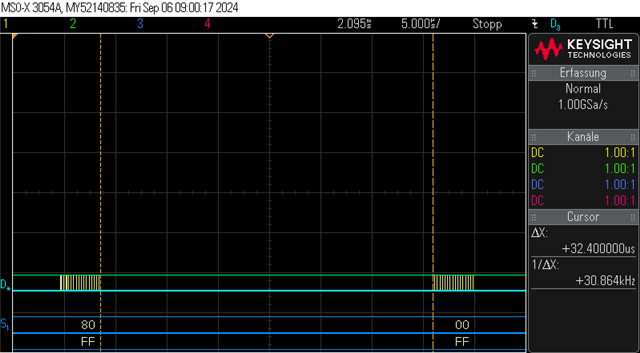
I am wondering why is there is big ~14us gap between bytes. From the red line I have highlighted, you can see SCK is just flat, waiting during this time, until it starts to clock again and we see the next byte from the slave (0x00), and then the same gap until the next byte (0x24).

I am wondering if this is to do with the MCU or some inefficiency in the SPI driver somewhere in the stack of nRFX drivers to Zephyr SPI API?

  • Hi John, 
    Can you show your code ? 
    Could you try to test with the sample from our Academy course to see if you can reproduce the issue. https://academy.nordicsemi.com/courses/nrf-connect-sdk-intermediate/lessons/lesson-5-serial-peripheral-interface-spi/topic/exercise-1-10/ (try inter_less5_exer1_solution)

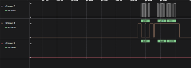
    I did a quick test here and I don't see the gap between bytes: 

    Here you see 1 byte write 0x88 before 2 bytes read. 

    I tested by adding the following code before bme_calibrationdata();

    	uint8_t values[3];
    	uint8_t size = 3;	
    	
    	uint8_t regaddr;
    	regaddr = CALIB00;
    	
    	while (1)
    	{
    		bme_read_reg(regaddr, values, size);
    		k_msleep(500);
    	}

  • Have a ongoing development for a bmp390 to merge into Zephyr. And have same problem with the SPI using SPIM3.

    On a 2Mhz bus have 30us where the clock stops for the second byte on a read register, make the read fail.

    Testing on a nrf5340.

    Update:
    I got my problem fixed. There was a extra dummy byte in the TX give me the response from the bmp390.
    Still wondering about the stop of the clock and the big delay.

  • Did you noticed that the clock stops? That should not happen.

  • Please try to reproduce the issue with the inter_less5_exer1_solution sample that I pointed to. The clock stop is indeed strange but we haven't been able to reproduce it with the sample. 

  • Hi  ,

    I think I have found the reason, let me explain. 

    I am using SPIM3 set to 8MHz, so any time waiting at this scale looks like quite a lot:

    Look at this function from the zephyr BMI270 driver. It performs a register read from the sensor. It sets up an array of 2 rx_buf structures. 

    The rx_buf[0] has 2 bytes length, 1 placeholder for the TX byte (register addr) and then the 1 dummy byte needed when reading from this sensor.

    The rx_buf[1] actually holds the data we want to read, so you see it takes length and pointer to data read.

    static int bmi270_reg_read_spi(const union bmi270_bus *bus, uint8_t start, uint8_t *data, uint16_t len)
    {
        int ret;
        uint8_t addr;
        uint8_t tmp[2];
        const struct spi_buf tx_buf = {
        .buf = &addr,
        .len = 1};
        const struct spi_buf_set tx = {
        .buffers = &tx_buf,
        .count = 1};
        struct spi_buf rx_buf[2];
        const struct spi_buf_set rx = {
        .buffers = rx_buf,
        .count = ARRAY_SIZE(rx_buf)};
        
        /* First byte we read should be discarded. */
        rx_buf[0].buf = &tmp;
        rx_buf[0].len = 2;
        rx_buf[1].len = len;
        rx_buf[1].buf = data;
        
        addr = start | 0x80;
        
        ret = spi_transceive_dt(&bus->spi, &tx, &rx);
        if (ret < 0)
        {
            LOG_DBG("spi_transceive failed %i", ret);
            return ret;
        }
        
        k_usleep(BMI270_SPI_ACC_DELAY_US);
        return 0;
    }

    On the bus though, we see the large gap is actually between each of these buffers. Once we start it starts long read (rx_buf[1], there are no gaps and it just keeps clocking.

    I tried to illustrate what is going on the bus here below with a single call to bmi270_reg_read_spi where rx_buf[1] len is something like 1000 bytes. You can see the waiting times are between the TX start adress, rx_buf[0] and then rx_buf[1]. 

    It seems like whenever there is a change in memory buffers, there is this wait time in between. I feel like this is maybe something at the nRFX driver level. I am wondering if this is simply unavoidable overhead setting up the DMA, or some kind of inefficiency.

    Let me know if this makes sense.

Related