Direction finding: PI shift in phase difference for 2M PHY

Hi!

I am using v2.6.1/nrf/samples/bluetoothdirection_finding_connectionless_tx/rx sample, and NCS v2.6.1 for AoA. I made some modification on the rx side to stream I/Q data via serial port, and read and calculate AoA on Ubuntu using a python script.

RX board: nrf5340 devkit + antenna

TX board: nrf5340/nrf52833 devkit

Antenna: 2 patterns with a distance of 5.3 cm (ant0: reference ant, ant1: sample ant), with settling time after switching within 100~250ns

Problem Description:

Right now the angle calculation works well if tx uses 1M PHY. But if I switch it to 2M, it will get wrong results. After looking into the phase data, I find a 180 degree shift for every calculated phase difference, so I manually eliminate that shift and then 2M works. I wonder if anyone has met the same problem and what could cause that, any thoughts will be appreciated!

About CTE configuration:

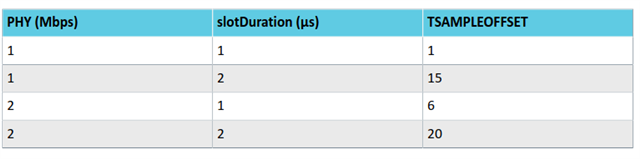
I am using 1 us sample slot for both 1M and 2M

TSAMPLESPACINGREF = 1us

TSAMPLESPACING = 2us

TSWITCHSPACING = 2us

Details of Calculation:

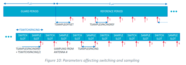
I have read the white paper nWP-036 and understand the antennas are going to be switched in order [0,0,0,0,0,0,0,0] (8 for ref period) followed by [1, 0, 1, 0, ...](sample period). Besides the reference period, I am also using the sample period for calibration since ant0 will be visited again during the sample period.

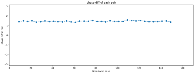
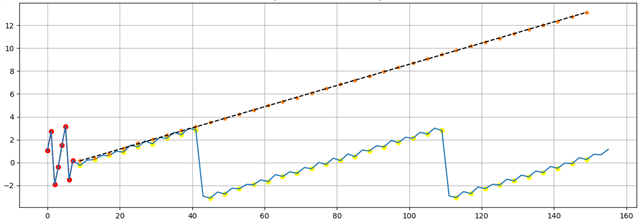
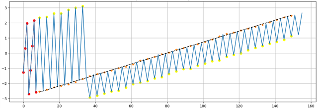
Here the figure (x-axis: time in us; y-axis: phase in rad) shows how I calculate the phase diff and AoA for a 160us CTE report when using 1M PHY. The red dots are phases of each I/Q data from ant0 during the reference period; and the dots marked as orange stars are the calibrated reference phases, which are prepared for phase difference calculation for each sample from ant1 (yellow dots); calculated phase diff will be shifted by N*2pi to make sure it is within range [-pi, pi]; finally calculated AoA using the arccos formula as the white paper does.

Note that the first sample during the ref period is aligned with time=0, and the first sample during the sample period (first yellow dot) is aligned with time=9 (equals to time of the last ref sample(7us) + TSAMPLESPACINGREF + TSWITCHSPACING/2, according to nWP-036), please correct me if I made any mistake.

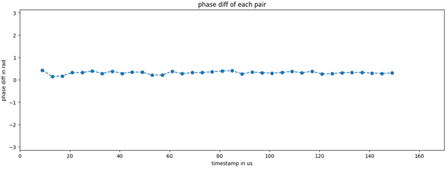
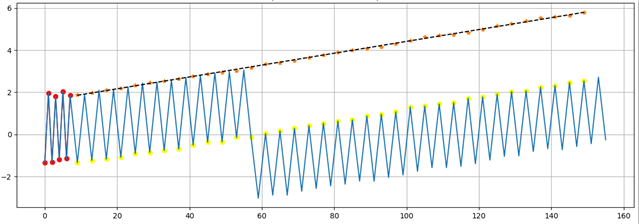
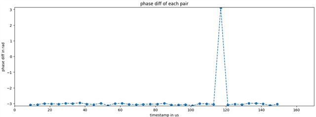
If using 2M PHY, the calculation should be the same as 1M theoretically, except the wavelength for calculating AoA will be different. But it turns out calculated phase diff with 2M PHY always gives a 180 degree shift.

  • I understand this is a long post, but please take some time to read through it, it might not be just another offset question you guys have answered. I appreciate you effort, thanks a lot!

    The full 180 degree phase shift I mentioned is not something related to that drifting or offset to 250k/500k, there might be some misunderstanding so please let me explain it.

    The offset you guys are talking about:

    For 1M PHY, the frequency of CTE signal in the baseband should be 250kHz + some offset (fΔ + foffset),

    If you look at the red dots (reference period) this plot, it represents an undersampled sinewave for 2 periods, each period of which lasts for about 4us with some shift caused by foffset. we can get the frequency of a sinewave with 4us period as 1s/4us = 250kHz, that exactly matches with (fΔ + foffset) if further taking the shift into consideration.

    The foffset can be calculated using the reference period and be compensated by the samples got from reference antenna during switching period. Slope of the dash line in plot shows the actual foffset calculated.

    After getting the actual frequency of CTE signal in the baseband, we can calculate phase angle of signal at reference antenna ant0 (orange stars) at each timestamp that ant1 gets sampled (yellow dots). One orange star and one yellow dot at the same timestamp are paired to calculate phase difference for each, and then AoA can be calculated from the results.

    For 2M PHY, the 4us period of sinewave becomes 2us, and we can calculate the frequency as 1s/2us = 500kHz. And we can calculate foffset by following a similar method as for 1M PHY.

    I am talking about a PI shift in phase difference:

    please read the calculated phase difference in this plot

    It shows a flat and stable phase difference for each pair of yellow dots and orange stars, that means foffset you guys said has been eliminated as expected. Although this plot is for 1M, but 2M shows similar flat and stable results, only with a PI shift as stated here:

    To be more clear, for example if calculating phase difference and aoa of the first yellow dot (Y1) and the first orange star (O1) in plot, it is 

    • phase_diff = phase_value_Y1 - phase_value_O1
    • aoa = arccos(phase_diff * wavelength / (2 * PI * pattern_distance))

    If assuming the tx is on the centre line of the two ant patterns of rx,

    • phase_diff should be 0, and then
    • aoa = arccos(0) = PI/2

    In 1M, the actual calculating is exactly like this. However if using 2M, "phase_diff = PI" is what I get.

    As for the rest pairs, there will be a PI shift in each calculated phase_diff.

    For your reference: both at position where AoA=PI/2

    1M:

    2M:

  • Hi,

    I digged into direction finding code, and I found something inconsistent between what's defined in NCS and the white paper, you might be interested in this.

    In file Kconfig.df under path ncs/v2.6.1/zephyr/subsys/bluetooth/controller/Kconfig.df.

    config BT_CTLR_DF_SWITCH_OFFSET
    	int "Antenna switch offset relative to end of CRC"
    	depends on SOC_COMPATIBLE_NRF
    	range -2048 2047
    	default 0
    	help
    	  Offset of start of antenna switching after end of the CRC. It is a signed value in number
    	  of 16M cycles. Decreasing the offset value beyond the trigger of the AoA/AoD procedure
    	  will have no effect.
    
    config BT_CTLR_DF_SAMPLE_OFFSET_PHY_1M_SAMPLING_1US
    	int "CTE sampling offset relative for PHY 1M and 1US samples spacing"
    	depends on SOC_COMPATIBLE_NRF
    	range -2048 2047
    	default 1
    	help
    	  Offset of sampling start from beginning of sampling slot. The value is a signed number
    	  of 16M cycles relative. It is used when PHY is set to PHY 1M and sampling slot duration
    	  is 1 us. Decreasing the offset beyond the trigger of the AoA/AoD procedure will have
    	  no effect.
    
    config BT_CTLR_DF_SAMPLE_OFFSET_PHY_2M_SAMPLING_1US
    	int "CTE sampling offset relative for PHY 1M and 1US samples spacing"
    	depends on SOC_COMPATIBLE_NRF
    	range -2048 2047
    	default 15
    	help
    	  Offset of sampling start from beginning of sampling slot. The value is a signed number
    	  of 16M cycles relative. It is used when PHY is set to PHY 1M and sampling slot duration
    	  is 1 us. Decreasing the offset beyond the trigger of the AoA/AoD procedure will have
    	  no effect.
    
    
    config BT_CTLR_DF_SAMPLE_OFFSET_PHY_1M_SAMPLING_2US
    	int "CTE sampling offset relative for PHY 1M and 2US samples spacing"
    	depends on SOC_COMPATIBLE_NRF
    	range -2048 2047
    	default 6
    	help
    	  Offset of sampling start from beginning of sampling slot. The value is a signed number
    	  of 16M cycles relative. It is used when PHY is set to PHY 1M and sampling slot duration
    	  is 2 us. Decreasing the offset beyond the trigger of the AoA/AoD procedure will have
    	  no effect.
    
    config BT_CTLR_DF_SAMPLE_OFFSET_PHY_2M_SAMPLING_2US
    	int "CTE sampling offset relative for PHY 1M and 2US samples spacing"
    	depends on SOC_COMPATIBLE_NRF
    	range -2048 2047
    	default 20
    	help
    	  Offset of sampling start from beginning of sampling slot. The value is a signed number
    	  of 16M cycles relative. It is used when PHY is set to PHY 1M and sampling slot duration
    	  is 2 us. Decreasing the offset beyond the trigger of the AoA/AoD procedure will have
    	  no effect.

    Default values for "BT_CTLR_DF_SAMPLE_OFFSET_PHY_2M_SAMPLING_1US" and "BT_CTLR_DF_SAMPLE_OFFSET_PHY_1M_SAMPLING_2US" in Kconfig.df differ from the white paper (also you should carefully check the comments under 'help'), I wonder which to trust.

    But according to the time shifting caused by TSAMPLEOFFSET as shown in this figure,

    I don't think a wrong value will result in the 180 degree phase difference shifting I mentioned in this post.

  • Okay Yue

    I've reported this to the dev team now so the devs are having a look at it. Unfortunately I don't have any input as of now, but would trust the NCs v2.6.1 version of the documentation since the white paper is a bit dated at this point, but please wait for confirmattion here.

    Best regards,

    Simon

  • Thanks for that! I will wait for your confirmation.

    And hope you will also have update on the 180 degree phase difference shifting issue.

  • Okay, so the white paper describes what out HW is capable of, not what the Bluetooth spec. or the samples do and is mainly intended for people looking to make their own solution. For the Bluetooth compliant solutions you use the SDK sample and documentation, and modify it from there. Use this and the Bluetooth SIG documentation for information on how that works. Things like the switching pattern in the WP is not correct according to the Bluetooth specification either, so you should only stick to the NCS documentation and Bluetooth SIG for Bluetooth compliant solutions.

    Best regards,

    Simon

Related