Migrating MQTT Sample to a Custom Board

Hi,

I have successfully built and ran the MQTT sample (/opt/nordic/ncs/v2.7.0/nrf/samples/net/mqtt) on the nRF9160-DK. I did have a few problems with SIM coverage and firmware versions which was sorted in this ticket.

 MQTT Sample Not Connecting on nRF9160 Board 

I would now like to move this code onto my own board.

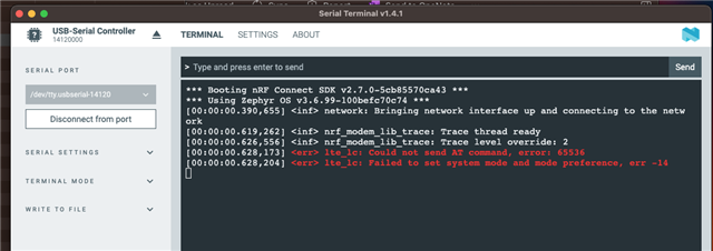
When I run this code on my own board, I see this error.

*** Booting nRF Connect SDK v2.7.0-5cb85570ca43 ***
*** Using Zephyr OS v3.6.99-100befc70c74 ***
[00:00:00.431,610] <inf> network: Bringing network interface up and connecting to the network
[00:00:00.658,813] <inf> nrf_modem_lib_trace: Trace thread ready
[00:00:00.666,107] <inf> nrf_modem_lib_trace: Trace level override: 2
[00:00:00.667,724] <err> lte_lc: Could not send AT command, error: 65536
[00:00:00.667,755] <err> lte_lc: Failed to set system mode and mode preference, err -14
+CEREG: 2
+CEREG: 4
+CEREG: 2,"B984","00542616",9
+CSCON: 1
+CEREG: 2,"B984","00542616",9,0,11
+CSCON: 0
 

My overlay file is shown below.

&pinctrl {
        uart0_default: uart0_default {
                group1 {
                        psels = <NRF_PSEL(UART_TX, 0, 6)>, <NRF_PSEL(UART_RX, 0, 7)>;
                };
        };

        uart0_sleep: uart0_sleep {
                group1 {
                        psels = <NRF_PSEL(UART_TX, 0, 6)>, <NRF_PSEL(UART_RX, 0, 7)>;
                        low-power-enable;
                };
        };
};

&uart0 {
        status = "okay";
        current-speed = < 115200 >;
        /delete-property/ rts-pin;
        /delete-property/ cts-pin;
};

/* Enable uart1 for tracing. */

&uart1 {
   status = "okay";
   current-speed = <1000000>;
   pinctrl-0 = <&uart1_default>;
   pinctrl-1 = <&uart1_sleep>;
   pinctrl-names = "default", "sleep";
};

/ {
   chosen {
      nordic,modem-trace-uart = &uart1;
   };
};

I use UART0 for my serial terminal.

Would appreciate your pointers on this,

Thanks,

Rod 

Parents
  • Hi Rod,

    Did you manage to collect a modem trace through either uart1 or RTT terminal?

    I see you also play with link monitor before. If this is a new custom board, are you able to see it can successfully connect with network when you check with link monitor after programming Serial LTE modem (nordicsemi.com)?

    Best regards,

    Charlie

  • Hi Charlie,

    No, I didn't manage to get the trace to work.

    I tried the serial LTE example,

    / {
    	chosen {
    		ncs,slm-uart = &uart1;
    	};
    };
    
    &uart0 {
    	status = "okay";
    	hw-flow-control;
    };
    
    &uart1 {
    	compatible = "nordic,nrf-uarte";
    	current-speed = <115200>;
    	status = "okay";
    
    	pinctrl-0 = <&uart1_default_alt>;
    	pinctrl-1 = <&uart1_sleep_alt>;
    	pinctrl-names = "default", "sleep";
    };


    &i2c2 {
    	status = "disabled";
    };
    
    &pinctrl {
    	uart1_default_alt: uart1_default_alt {
    		group1 {
    			psels = <NRF_PSEL(UART_RX, 0, 7)>;
    			bias-pull-up;
    		};
    		group2 {
    			psels = <NRF_PSEL(UART_TX, 0, 6)>;
    		};
    	};
    
    	uart1_sleep_alt: uart1_sleep_alt {
    		group1 {
    			psels = <NRF_PSEL(UART_TX, 0, 6)>,
    				<NRF_PSEL(UART_RX, 0, 7)>;
    			low-power-enable;
    		};
    	};
    };
    

    I am using my own overlay file, above to redirect the serial. terminal.

    Im getting this as an output

    All pins have been configured as non-secure
    [Sec Thread] Secure image initializing!
    TF-M Float ABI: Hard
    Lazy stacking enabled
    Booting TF-M v2.0.0-ncs2
    Ready

    Rod

  • Hi Rod,

    Let me explain the setup in the original sample to help you understand your custom board setting.

    nrf/snippets/nrf91-modem-trace-uart/modem-trace-uart.overlay is used when modem trace is enabled in the official sample. It uses uart1 for modem trace.

    The default SLM sample use uart0 for terminal communication and uart1 for TF-M log output, so you need to use nrf/snippets/tfm-enable-share-uart/overlay-tfm-enable-share-uart.conf to make TF-M use uart0 as well when modem trace through uart1 is enabled.

    Snippets for an nRF91 Series device (nordicsemi.com)

    https://docs.nordicsemi.com/bundle/ncs-2.7.0/page/nrf/libraries/modem/nrf_modem_lib/nrf_modem_lib_trace.html#sending_traces_over_uart_on_a_custom_board

    The above overly you have shared is trying to switch uart1 and uart0 functions, you need to copy nrf/snippets/nrf91-modem-trace-uart/modem-trace-uart.overlay here and replace uart1 with uart0 for modem trace collection.

    Best regards,

    Charlie

Reply Children
  • Hi Charlie,

    Thanks for the pointers. I have updated my overlay file as below.

    / {
       chosen {
          nordic,modem-trace-uart = &uart1;
       };
    };
    
    &uart0 {
    	status = "okay";
    	current-speed = < 115200 >;
    	pinctrl-0 = <&uart0_default>;
       	pinctrl-1 = <&uart0_sleep>;
       	pinctrl-names = "default", "sleep";
    	/delete-property/ rts-pin;
    	/delete-property/ cts-pin;
    };
    
    /* Enable uart1 for tracing. */
    
    
    &uart1 {
       	status = "okay";
       	current-speed = <1000000>;
       	pinctrl-0 = <&uart1_default_alt>;
       	pinctrl-1 = <&uart1_sleep_alt>;
       	pinctrl-names = "default", "sleep";
    	/delete-property/ rts-pin;
    	/delete-property/ cts-pin;
    };
    
    
    &pinctrl {
    	uart0_default: uart0_default {
    		group1 {
    			psels = <NRF_PSEL(UART_TX, 0, 6)>, <NRF_PSEL(UART_RX, 0, 7)>;
    		};
    	};
    
    	uart0_sleep: uart0_sleep {
    		group1 {
    			psels = <NRF_PSEL(UART_TX, 0, 6)>, <NRF_PSEL(UART_RX, 0, 7)>;
    			low-power-enable;
    		};
    	};
    };
    
    &pinctrl {
    	uart1_default_alt: uart1_default_alt {
    		group1 {
    			psels = <NRF_PSEL(UART_RX, 0, 14)>;
    			bias-pull-up;
    		};
    		group2 {
    			psels = <NRF_PSEL(UART_TX, 0, 13)>;
    		};
    	};
    
    	uart1_sleep_alt: uart1_sleep_alt {
    		group1 {
    			psels = <NRF_PSEL(UART_TX, 0, 14)>,
    				<NRF_PSEL(UART_RX, 0, 13)>;
    			low-power-enable;
    		};
    	};
    };


    Which has enabled me to see output on my terminal,

     and looks like trace is working. 

    This is my trace file.

    trace-2024-09-18T14-24-19.592Z.mtrace

    Rod

  • Hi Rod,

    I am not able to open your provided trace file. Are you able to open trace file in Wireshark on your end?

    Best regards,
    Dejan

  • Hi Dejan,

    Sorry for the delay in getting back to you, i have been on holiday.

    I have tried to open the file in Wireshark and am unable too. To check, i had a look at other .mtrace files that others have uploaded and tried the trace file on this ticket.

     RE: STUCK LTE Connection 

    I was unable to open that file.

    When i look at the types of files that Wireshark open, i dont see .mtrace ?

    Do i need to create a different type of trace? How do  do that?

    Rod

  • Hi Rod,

    You might not have taken traces correctly or somehow trace file got corrupted. Can you try to do it again? Please have a look at instructions on how to capture modem trace in our Cellular IoT Fundamentals course. It should be possible to upload file in mtrace format.

    Best regards,
    Dejan

  • Hi Dejan,

    I started by trying this process using the nRF9169DK board

    I produced this trace file

    trace-2024-10-17T12-47-05.939Z.mtrace

    which opened automatically in Waveshark.

    I noticed that I was unable to subsequently open the same file in Waveshark but had to open the file that had been saved in Waveshark.

    nrf9160_WS.pcapng

    Anyway, this seems to work OK.

    I then tried this on my own board using the same process and this is where i see problems.

    Although I seem to be generating a .mtrace file, Waveshark reports no data.

    Im guessing I have something wrong with my UART set up?

    This is my overlay file 

    / {
       chosen {
          nordic,modem-trace-uart = &uart1;
       };
    };
    
    &uart0 {
    	status = "okay";
    	current-speed = < 115200 >;
    	pinctrl-0 = <&uart0_default>;
       	pinctrl-1 = <&uart0_sleep>;
       	pinctrl-names = "default", "sleep";
    	/delete-property/ rts-pin;
    	/delete-property/ cts-pin;
    };
    
    /* Enable uart1 for tracing. */
    
    
    &uart1 {
       	status = "okay";
       	current-speed = <1000000>;
       	pinctrl-0 = <&uart1_default_alt>;
       	pinctrl-1 = <&uart1_sleep_alt>;
       	pinctrl-names = "default", "sleep";
    	/delete-property/ rts-pin;
    	/delete-property/ cts-pin;
    };
    
    
    &pinctrl {
    	uart0_default: uart0_default {
    		group1 {
    			psels = <NRF_PSEL(UART_TX, 0, 6)>, <NRF_PSEL(UART_RX, 0, 7)>;
    		};
    	};
    
    	uart0_sleep: uart0_sleep {
    		group1 {
    			psels = <NRF_PSEL(UART_TX, 0, 6)>, <NRF_PSEL(UART_RX, 0, 7)>;
    			low-power-enable;
    		};
    	};
    };
    
    &pinctrl {
    	uart1_default_alt: uart1_default_alt {
    		group1 {
    			psels = <NRF_PSEL(UART_RX, 0, 14)>;
    			bias-pull-up;
    		};
    		group2 {
    			psels = <NRF_PSEL(UART_TX, 0, 13)>;
    		};
    	};
    
    	uart1_sleep_alt: uart1_sleep_alt {
    		group1 {
    			psels = <NRF_PSEL(UART_TX, 0, 14)>,
    				<NRF_PSEL(UART_RX, 0, 13)>;
    			low-power-enable;
    		};
    	};
    };


    Regards,

    Rod

Related