
Hello,
I am using the nPM1300 in my hardware design along the nRF52840 and a battery from Renata (ICP622540PMT).
All the power outputs of the nPM1300 are in use (LDO1, LDO2, Buck1, Buck2, VSYS).
During hardware design I used the reference circuits as provided in the datasheet (configuration 1).
I have ordered the EK as well for some testing and after inspecting the hardware of the EK I noticed some differences between EK and the recommended capacitors from the datasheet.
- Capacitor connected to VBAT: In the datasheet all reference designs have C6 with 2.2 µF connected to pin VBAT. In the schematic of the EK the capacitor connected to VBAT has 4.7 µF. Why has the EK a different value for C6 compared to what information is provided in the datasheet of the nPM1300?
- Capacitors at VOUT: this questions splits into two related questions.
-
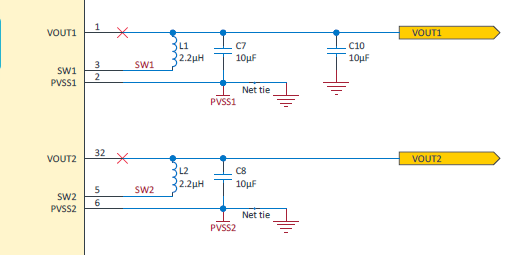
Additional Capacitor at VOUT1 (EK): In the datasheet only one 10 µF capacitor is recommended for VOUT1 (and VOUT2). In the EK I can find two 10 µF capacitors connected to VOUT1. What is the reason for the second capacitor?
-
Capacitors at EK VOUT1 vs VOUT2: at the EK the pin VOUT1 has two capacitors (as stated above), but VOUT2 only has one capacitor. Where does this difference come from?
-
Image Question 1 - from EK documentation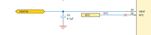
Image Question 2 - from EK documentation
Thanks in advance for any input regarding my questions!
Markus
