Unexpected Power Spikes in "System ON" Sleep Mode and High Power Consumption in Sleep Mode on nRF52840dk

Hi there,

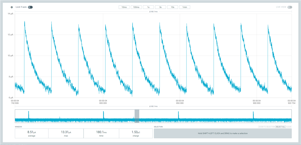
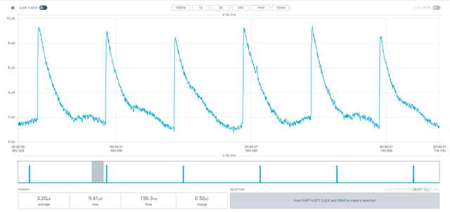
Thanks for helping. We are using the nRF52840 DK along with the Power Profiler Kit 2 (PPK2) for power measurement. We are encountering periodic power spikes during the "System ON" sleep mode that do not match the expected power consumption specified in the datasheet. According to the nRF52840 specifications, the current consumption in "System ON" sleep mode should remain stable in the range of 1-3 µA. However, we are observing periodic spikes that reach up to 13 µA, with an average current of approximately 8.51 µA.(Nrf only mode in nordic 52840dk)

Attached is a power profile diagram that illustrates the unexpected current spikes during sleep mode.

Steps Taken:

  1. Peripheral Disabling: We ensured that all unnecessary peripherals (such as ADC, TWI, LOG, UART, and GPIOTE) were disabled. We also confirmed that no EasyDMA-related activities were running.

  2. Resetting DIF: We reset the Debug Interface (DIF) using both power cycling and the SWD command:

    shell
    Copy code
    SWDSelect SWDWriteDP 1 0x04000000 exit

    This was done to minimise any interface current on the nRF52840.

  3. Sleep Mode Entry: We confirmed that the system is entering sleep mode by using nrf_pwr_mgmt_run() in the main code. We also enabled a debug pin and monitored pin 31 to ensure that the sleep mode is properly entered (a high signal on pin 31 indicates sleep mode is active).

  4. GPIO Configuration: All unused GPIOs were configured with pull-down resistors to avoid floating inputs that could draw additional current.

Despite these optimizations, the power profile still shows periodic current spikes with a maximum of around 13.31 µA, significantly higher than the expected flat power consumption during sleep. The system does not appear to be achieving the low power levels we anticipated.

Questions:

  • Based on the attached power profile, could you suggest any additional steps we might take to identify the cause of these power spikes?
  • Could there be any internal processes, interrupts, or hardware configurations that are leading to these spikes in current during sleep mode?
  • Are there specific settings related to GPIO or other peripherals that could be drawing additional power in sleep mode that we might have overlooked?

Parents
  • Hi Alan, 

    You can take a look here, the spikes are the consumption when the chip is in LDO / DCDC in refresh mode. 

    However, the readings you have of average consumption of 8.51uA is quite high. 
    Have you got another DK to test ? 
    Which firmware did you use to test ? My go to firmware to test power consumption is the peripheral_lbs with prj_minimal.conf.  It's the configuration optimized for both minimum flash and minimum power consumption (for BLE). 
    You should be able to see good sleeping current between BLE activities. 
    For example here is the result in my test (Ampere meter mode): 


    I would also suggest to try powering the board using a battery, just in case you have noise introduced by the USB connection. 

  • Hi Huang,

    Thank you for your prompt and insightful response.

    we’ve reviewed the attached diagram, and we can confirm that the periodic spike pattern in your profile is indeed similar to what we are observing. However, in your case, the average current between spikes appears to be much closer to the expected range of 1-3 µA, whereas we are still seeing around 6-7 µA.

    We’d like to seek further clarification and advice on the following points:

    1. LDO / DCDC Refresh Mode:
    Based on your explanation and the provided resources, can we assume that these periodic spikes due to the LDO / DCDC refresh mode are a normal pattern for the nRF52840 DK in "System ON" sleep mode? In other words, should we focus on the flatter portions of the power profile (between the spikes) for our average power consumption measurements and essentially ignore the spikes? If so, we are considering calculating the average consumption by excluding the spikes. Does this approach seem valid?

    2. Additional DK Testing:
    We can confirm that we’ve tested the power consumption on another brand-new nRF52840 DK, and we’re seeing the same results, which suggests the issue is not hardware-specific.

    3. Firmware Setup:
    To isolate the high power consumption issue, we’ve used a very simple test example:

    We are toggling LED2 and using RTC with LFCLK to periodically enter sleep mode between duty cycles.
    We have ensured that no unnecessary peripherals (such as BLE, TWI, LOG, UART, etc.) are initialized or included in the firmware.(sdk_config.h)

    4. Measurement Setup:

    We just also tried using the current mode, after we received your reply: we cut SB40 and connect vin and vout to p22 (52840dk), we got similar results as before.


    For the power measurement:

    We are using the source meter mode on the PPK2 (3V) and have set SW6 to nRF-only mode.
    We have also disconnected the USB to avoid additional power consumption from the interface.

    5. Next Steps – Reducing Base Power Consumption:
    If you could confirm that we can disregard the LDO/DCDC spikes as part of the normal refresh cycle, our focus will shift to reducing the base power consumption, which currently sits around 6-7 µA. We are aiming to bring this down to the expected range of 1-3 µA.

    Based on our current setup (no BLE, minimal peripherals, LFCLK, and simple duty cycling), do you have any further suggestions or best practices that could help us achieve this lower baseline consumption? we attached the firmawre below and let me know what we could provide to clearify our problems. Thanks!

    we are using Segger:

    #include <stdint.h>
    #include <stdbool.h>
    #include "nrf.h"
    #include "nrf_drv_rtc.h"
    #include "nrf_drv_clock.h"
    #include "nrf_gpio.h"
    #include "boards.h"
    #include "nrf_pwr_mgmt.h"
    #include "nrfx_power.h"
    
    #ifdef BSP_LED_1
    #define COMPARE_EVENT_OUTPUT BSP_LED_1 /**< Pin number for indicating compare event. */
    #else
    #error "Please define output pin (BSP_LED_1)"
    #endif
    
    // Forward declaration of static functions
    static void configure_unused_gpios(void);
    static void lfclk_init(void);
    static void rtc_init(void);
    static void power_management_init(void);
    static void rtc_handler(nrf_drv_rtc_int_type_t int_type);
    
    /**
    * @brief Initialize the LEDs on the board.
    */
    static void leds_config(void) {
    bsp_board_init(BSP_INIT_LEDS); // Initialise the LED functionality
    }
    
    /**
    * @brief Configure unused GPIOs for low power.
    * @note This function configures both Port 0 and Port 1.
    */
    static void configure_unused_gpios(void) {
    // Configure all GPIOs (Port 0 and Port 1, pin 0 to 47)
    for (uint32_t pin = 0; pin < 48; pin++) {
    if (nrf_gpio_pin_dir_get(pin) == NRF_GPIO_PIN_DIR_INPUT &&
    nrf_gpio_pin_read(pin) == 0) {
    nrf_gpio_cfg_input(pin, NRF_GPIO_PIN_PULLDOWN);
    }
    }
    }
    
    /**
    * @brief Initialize the LFCLK for RTC operation.
    * @note The LFCLK (Low Frequency Clock) is required for the RTC.
    */
    static void lfclk_init(void) {
    ret_code_t err_code = nrf_drv_clock_init();
    APP_ERROR_CHECK(err_code);
    
    // Request the low-frequency clock
    nrf_drv_clock_lfclk_request(NULL);
    while (!nrf_clock_lf_is_running()) {
    // Wait for the clock to start running
    }
    }
    
    /**
    * @brief RTC interrupt handler.
    * @param int_type Interrupt type triggered by RTC
    */
    static void rtc_handler(nrf_drv_rtc_int_type_t int_type) {
    if (int_type == NRF_DRV_RTC_INT_COMPARE0) {
    nrf_gpio_pin_toggle(COMPARE_EVENT_OUTPUT); // Toggle LED state on compare event
    uint32_t current_counter = nrf_drv_rtc_counter_get(&rtc);
    ret_code_t err_code = nrf_drv_rtc_cc_set(&rtc, 0, current_counter + 24, true); // 3 seconds 24*1/8
    APP_ERROR_CHECK(err_code);
    }
    }
    
    /**
    * @brief Initialize the RTC2 instance with a prescaler.
    */
    static void rtc_init(void) {
    nrf_drv_rtc_config_t rtc_config = NRF_DRV_RTC_DEFAULT_CONFIG;
    rtc_config.prescaler = 4095; // 8 Hz tick frequency
    
    ret_code_t err_code = nrf_drv_rtc_init(&rtc, &rtc_config, rtc_handler);
    APP_ERROR_CHECK(err_code);
    
    nrf_drv_rtc_int_enable(&rtc, NRF_RTC_INT_COMPARE0_MASK);
    nrf_drv_rtc_enable(&rtc);
    
    // Schedule first compare event after 3 seconds
    uint32_t current_counter = nrf_drv_rtc_counter_get(&rtc);
    err_code = nrf_drv_rtc_cc_set(&rtc, 0, current_counter + 24, true);
    APP_ERROR_CHECK(err_code);
    }
    
    /**
    * @brief Initialize power management, including DC/DC configuration.
    */
    static void power_management_init(void) {
    // Set up power management with DC/DC converter
    nrfx_power_config_t power_config = {
    .dcdcen = true, // Enable DC/DC converter
    .dcdcenhv = false // Disable DC/DC high voltage mode
    };
    nrfx_power_init(&power_config);
    
    // Initialize power management library
    ret_code_t ret_code = nrf_pwr_mgmt_init();
    APP_ERROR_CHECK(ret_code);
    }
    
    /**
    * @brief Main function.
    */
    int main(void) {
    // Initialize peripherals and power management
    leds_config();
    configure_unused_gpios();
    lfclk_init();
    rtc_init();
    power_management_init();
    
    // Main loop
    while (true) {
    // Enter low-power mode; handles pending tasks and ensures proper power management
    nrf_pwr_mgmt_run();
    }
    }
Reply
  • Hi Huang,

    Thank you for your prompt and insightful response.

    we’ve reviewed the attached diagram, and we can confirm that the periodic spike pattern in your profile is indeed similar to what we are observing. However, in your case, the average current between spikes appears to be much closer to the expected range of 1-3 µA, whereas we are still seeing around 6-7 µA.

    We’d like to seek further clarification and advice on the following points:

    1. LDO / DCDC Refresh Mode:
    Based on your explanation and the provided resources, can we assume that these periodic spikes due to the LDO / DCDC refresh mode are a normal pattern for the nRF52840 DK in "System ON" sleep mode? In other words, should we focus on the flatter portions of the power profile (between the spikes) for our average power consumption measurements and essentially ignore the spikes? If so, we are considering calculating the average consumption by excluding the spikes. Does this approach seem valid?

    2. Additional DK Testing:
    We can confirm that we’ve tested the power consumption on another brand-new nRF52840 DK, and we’re seeing the same results, which suggests the issue is not hardware-specific.

    3. Firmware Setup:
    To isolate the high power consumption issue, we’ve used a very simple test example:

    We are toggling LED2 and using RTC with LFCLK to periodically enter sleep mode between duty cycles.
    We have ensured that no unnecessary peripherals (such as BLE, TWI, LOG, UART, etc.) are initialized or included in the firmware.(sdk_config.h)

    4. Measurement Setup:

    We just also tried using the current mode, after we received your reply: we cut SB40 and connect vin and vout to p22 (52840dk), we got similar results as before.


    For the power measurement:

    We are using the source meter mode on the PPK2 (3V) and have set SW6 to nRF-only mode.
    We have also disconnected the USB to avoid additional power consumption from the interface.

    5. Next Steps – Reducing Base Power Consumption:
    If you could confirm that we can disregard the LDO/DCDC spikes as part of the normal refresh cycle, our focus will shift to reducing the base power consumption, which currently sits around 6-7 µA. We are aiming to bring this down to the expected range of 1-3 µA.

    Based on our current setup (no BLE, minimal peripherals, LFCLK, and simple duty cycling), do you have any further suggestions or best practices that could help us achieve this lower baseline consumption? we attached the firmawre below and let me know what we could provide to clearify our problems. Thanks!

    we are using Segger:

    #include <stdint.h>
    #include <stdbool.h>
    #include "nrf.h"
    #include "nrf_drv_rtc.h"
    #include "nrf_drv_clock.h"
    #include "nrf_gpio.h"
    #include "boards.h"
    #include "nrf_pwr_mgmt.h"
    #include "nrfx_power.h"
    
    #ifdef BSP_LED_1
    #define COMPARE_EVENT_OUTPUT BSP_LED_1 /**< Pin number for indicating compare event. */
    #else
    #error "Please define output pin (BSP_LED_1)"
    #endif
    
    // Forward declaration of static functions
    static void configure_unused_gpios(void);
    static void lfclk_init(void);
    static void rtc_init(void);
    static void power_management_init(void);
    static void rtc_handler(nrf_drv_rtc_int_type_t int_type);
    
    /**
    * @brief Initialize the LEDs on the board.
    */
    static void leds_config(void) {
    bsp_board_init(BSP_INIT_LEDS); // Initialise the LED functionality
    }
    
    /**
    * @brief Configure unused GPIOs for low power.
    * @note This function configures both Port 0 and Port 1.
    */
    static void configure_unused_gpios(void) {
    // Configure all GPIOs (Port 0 and Port 1, pin 0 to 47)
    for (uint32_t pin = 0; pin < 48; pin++) {
    if (nrf_gpio_pin_dir_get(pin) == NRF_GPIO_PIN_DIR_INPUT &&
    nrf_gpio_pin_read(pin) == 0) {
    nrf_gpio_cfg_input(pin, NRF_GPIO_PIN_PULLDOWN);
    }
    }
    }
    
    /**
    * @brief Initialize the LFCLK for RTC operation.
    * @note The LFCLK (Low Frequency Clock) is required for the RTC.
    */
    static void lfclk_init(void) {
    ret_code_t err_code = nrf_drv_clock_init();
    APP_ERROR_CHECK(err_code);
    
    // Request the low-frequency clock
    nrf_drv_clock_lfclk_request(NULL);
    while (!nrf_clock_lf_is_running()) {
    // Wait for the clock to start running
    }
    }
    
    /**
    * @brief RTC interrupt handler.
    * @param int_type Interrupt type triggered by RTC
    */
    static void rtc_handler(nrf_drv_rtc_int_type_t int_type) {
    if (int_type == NRF_DRV_RTC_INT_COMPARE0) {
    nrf_gpio_pin_toggle(COMPARE_EVENT_OUTPUT); // Toggle LED state on compare event
    uint32_t current_counter = nrf_drv_rtc_counter_get(&rtc);
    ret_code_t err_code = nrf_drv_rtc_cc_set(&rtc, 0, current_counter + 24, true); // 3 seconds 24*1/8
    APP_ERROR_CHECK(err_code);
    }
    }
    
    /**
    * @brief Initialize the RTC2 instance with a prescaler.
    */
    static void rtc_init(void) {
    nrf_drv_rtc_config_t rtc_config = NRF_DRV_RTC_DEFAULT_CONFIG;
    rtc_config.prescaler = 4095; // 8 Hz tick frequency
    
    ret_code_t err_code = nrf_drv_rtc_init(&rtc, &rtc_config, rtc_handler);
    APP_ERROR_CHECK(err_code);
    
    nrf_drv_rtc_int_enable(&rtc, NRF_RTC_INT_COMPARE0_MASK);
    nrf_drv_rtc_enable(&rtc);
    
    // Schedule first compare event after 3 seconds
    uint32_t current_counter = nrf_drv_rtc_counter_get(&rtc);
    err_code = nrf_drv_rtc_cc_set(&rtc, 0, current_counter + 24, true);
    APP_ERROR_CHECK(err_code);
    }
    
    /**
    * @brief Initialize power management, including DC/DC configuration.
    */
    static void power_management_init(void) {
    // Set up power management with DC/DC converter
    nrfx_power_config_t power_config = {
    .dcdcen = true, // Enable DC/DC converter
    .dcdcenhv = false // Disable DC/DC high voltage mode
    };
    nrfx_power_init(&power_config);
    
    // Initialize power management library
    ret_code_t ret_code = nrf_pwr_mgmt_init();
    APP_ERROR_CHECK(ret_code);
    }
    
    /**
    * @brief Main function.
    */
    int main(void) {
    // Initialize peripherals and power management
    leds_config();
    configure_unused_gpios();
    lfclk_init();
    rtc_init();
    power_management_init();
    
    // Main loop
    while (true) {
    // Enter low-power mode; handles pending tasks and ensures proper power management
    nrf_pwr_mgmt_run();
    }
    }
Children
  • The pin configuration in the code above is not configuring all the pins, only those already in input mode reading 0 which is probably not what you wish as the reset configuration is 0x0002 which is input disconnected (and yes it is supposed to read '0' if disconnected but that does not look safe to me). I checked all the modes on the nRF52832 and nRF52840, though only have the results to hand for the nRF52832 though both were similar. The pull-up and pull-down apply to the port pin regardless of port direction, input or output, contradicting the manual. However, that might not always be the case for future die revisions. I found that actively driving an unused pin low was the best course of action to avoid input float, although setting t0 input with pull-down enabled was just as good.

    // Here are my measurement results, which prove the pullup/pull-down resistor is connected to the pin regardless
    // of the input setting. nRF52832, 32MHz crystal, no 32kHz crystal, no Reset pin, SoftDevice loaded but not
    // enabled, no peripherals enabled, idle. Power CR2032 coin cell, no ground other than PPK-2, no J-Link.
    //
    // This first table is default port settings after a reset, no changes:
    //
    // PPK-2  Meter  Conditions
    // ====== ====== ==========
    // 1.66uA 2.971V with errata workarounds, no i/o
    // 1.51uA 2.985V   no errata workarounds, no i/o
    //
    // This Next table is port settings made after a reset, all 32 port pins identical, nothing connected to any of
    // the 32 port pins, no errata applied:
    //
    // PPK-2  Meter   Direction    Input            Pullup         Drive Level      Sense Level    Output
    // ====== ======  ==========   ==============   ============   ==============   ============== ===========
    //
    // 1.49uA 2.989V (PIN_OUTPUT | PIN_DISCONNECT | PIN_PULLNONE | PIN_DRIVE_S0S1 | PIN_SENSE_OFF) Driven Low
    // 1.49uA 2.999V (PIN_OUTPUT | PIN_DISCONNECT | PIN_PULLDOWN | PIN_DRIVE_S0S1 | PIN_SENSE_OFF) Driven Low
    // 6.47mA 2.894V (PIN_OUTPUT | PIN_DISCONNECT | PIN_PULLUP   | PIN_DRIVE_S0S1 | PIN_SENSE_OFF) Driven Low
    // 6.47mA 2.889V (PIN_OUTPUT | PIN_CONNECT    | PIN_PULLUP   | PIN_DRIVE_S0S1 | PIN_SENSE_OFF) Driven Low
    //
    // 1.51uA 2.959V (PIN_OUTPUT | PIN_DISCONNECT | PIN_PULLNONE | PIN_DRIVE_S0S1 | PIN_SENSE_OFF) Driven High
    // 6.42mA 2.877V (PIN_OUTPUT | PIN_DISCONNECT | PIN_PULLDOWN | PIN_DRIVE_S0S1 | PIN_SENSE_OFF) Driven High
    // 1.53uA 2.938V (PIN_OUTPUT | PIN_DISCONNECT | PIN_PULLUP   | PIN_DRIVE_S0S1 | PIN_SENSE_OFF) Driven High
    //
    //
    // This shows setting a port pin into active low output driven low is as good as leaving a pin floating
    // when unused, with the added benefit that there is no possibility of port feedthrough if a floating pin
    // drifts through the threshold.
    //
    // Looking at pull-up and pull down resistor values for the 32 pins:
    //
    //   (2.877Volts / 6.42mA) * 32 ==> 14.34K Ohm
    

  • Hi Alan, 

    Alan said:
    Based on your explanation and the provided resources, can we assume that these periodic spikes due to the LDO / DCDC refresh mode are a normal pattern for the nRF52840 DK in "System ON" sleep mode? In other words, should we focus on the flatter portions of the power profile (between the spikes) for our average power consumption measurements and essentially ignore the spikes?

    Correct. But you shouldn't ignore the spikes. It's how the chip mainly consume power and regulate it for different components inside. 

    Alan said:
    If so, we are considering calculating the average consumption by excluding the spikes. Does this approach seem valid?

    The spikes should be used to calculate consumption. But you need to low down the base current. I am not sure why it has a base of above 6uA in your case.


    I assume you are using nRF5 SDK v17 ? Please try testing using \examples\peripheral\rtc example. After that try \examples\ble_peripheral\ble_app_proximity. Please send us the power profiling trace for each case. 


    Please try to double check with another way of measuring current. Just in case there is an issue with the PPK2. For sleep current, you can have quite accurate number even with a multimeter (Amprere meter mode). At least it can tell between 8uA and 3uA average current. Or you can use oscilloscope or power analyzer. 

Related