nrf52840 going into fault continously

Hi, I am trying to run DHCP Client example using ethernet w5500 and my nrf is continously going into fault. sometimes it gets the ip correctly and goes into fault and other times when it starts immediately goes into fault. 

I have ran same code on nrf52832 and it works fine, even tries it on nrf9160 and works fine, the issue occur on this one 

any insights on this ?

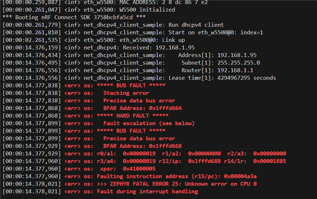
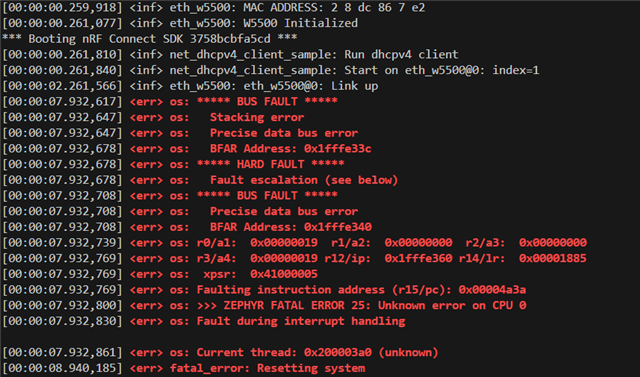
This pictures shows it got the IP from router and went into fault 

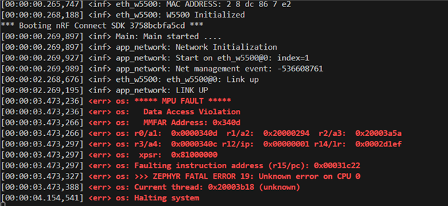
This picture shows it went into fault in the start

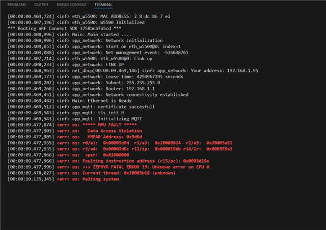
I tried running mqtt with ethernet and was going into fault as well and mqtt with ethernet works fine on nrf52832 

Also I tried increasing stack size and also given alot of heap but same issue, so it is definitly not related to that.

Parents
  • This whole lesson from DevAcademy would be beneficial. In your particular case, focus on the bit about the addr2line utility.

    https://academy.nordicsemi.com/courses/nrf-connect-sdk-intermediate/lessons/lesson-2-debugging/topic/exercise-2-11/

    You dont have to do anything in firmware to use it, you basically just plug in those instruction addresses and it will take you to the line of code that is causing the issues. Just eyeballing it, the error is originating from the same line of code regardless of if it's happening on boot or later on after the IP is printed. Also, based on some of those other addresses, it is likely a function using a null pointer to try and do something.

    Good luck!

  • Thanks alot for this. So I ran the addr2line command like this 

    backtrace comes to internal library. 

    Ima investigate it further.

  • This time it failed now before getting address from DNS, but as you can see faulting instruction address is same 

    7418.zephyr.map

    5543.zephyr_final.map

    this is outside for addr2line 

  • Hi,


    The content of LR is inside w5500_spi_read:


     .text.w5500_spi_read
                    0x000000000003593a       0x72 zephyr/drivers/ethernet/libdrivers__ethernet.a(eth_w5500.c.obj)

    And the content of PC is inside memcpy:

     .text.memcpy   0x000000000003d14c       0x1c F:/ncs/toolchains/cf2149caf2/opt/zephyr-sdk/arm-zephyr-eabi/arm-zephyr-eabi/lib/thumb/v7e-m/nofp\libc_nano.a(lib_a-memcpy-stub.o)
                    0x000000000003d14c                memcpy
    And your faulting thread is the internal thread of the w5500 runtime structure.


    Could you share your build/zephyr/.config file and build/zephyr/zephyr.dts file?


    Kind regards,

    Håkon

  • Here is .config file and .config.old file as well and .dts file. It was not allowing me to upload the file so I made zip and all the files are inside it 

    .config and dts file.rar

    And ethernet is connected to spi3(arduino spi) 

  • nrf52840 dts

    /*
     * Copyright (c) 2017 Linaro Limited
     *
     * SPDX-License-Identifier: Apache-2.0
     */
    
    /dts-v1/;
    #include <nordic/nrf52840_qiaa.dtsi>
    #include "nrf52840dk_nrf52840-pinctrl.dtsi"
    #include <zephyr/dt-bindings/input/input-event-codes.h>
    
    / {
    	model = "Nordic nRF52840 DK NRF52840";
    	compatible = "nordic,nrf52840-dk-nrf52840";
    
    	chosen {
    		zephyr,console = &uart0;
    		zephyr,shell-uart = &uart0;
    		zephyr,uart-mcumgr = &uart0;
    		zephyr,bt-mon-uart = &uart0;
    		zephyr,bt-c2h-uart = &uart0;
    		zephyr,sram = &sram0;
    		zephyr,flash = &flash0;
    		zephyr,code-partition = &slot0_partition;
    		zephyr,ieee802154 = &ieee802154;
    	};
    
    	leds {
    		compatible = "gpio-leds";
    		led0: led_0 {
    			gpios = <&gpio0 13 GPIO_ACTIVE_LOW>;
    			label = "Green LED 0";
    		};
    		led1: led_1 {
    			gpios = <&gpio0 14 GPIO_ACTIVE_LOW>;
    			label = "Green LED 1";
    		};
    		led2: led_2 {
    			gpios = <&gpio0 15 GPIO_ACTIVE_LOW>;
    			label = "Green LED 2";
    		};
    		led3: led_3 {
    			gpios = <&gpio0 16 GPIO_ACTIVE_LOW>;
    			label = "Green LED 3";
    		};
    	};
    
    	pwmleds {
    		compatible = "pwm-leds";
    		pwm_led0: pwm_led_0 {
    			pwms = <&pwm0 0 PWM_MSEC(20) PWM_POLARITY_INVERTED>;
    		};
    	};
    
    	buttons {
    		compatible = "gpio-keys";
    		button0: button_0 {
    			gpios = <&gpio0 11 (GPIO_PULL_UP | GPIO_ACTIVE_LOW)>;
    			label = "Push button switch 0";
    			zephyr,code = <INPUT_KEY_0>;
    		};
    		button1: button_1 {
    			gpios = <&gpio0 12 (GPIO_PULL_UP | GPIO_ACTIVE_LOW)>;
    			label = "Push button switch 1";
    			zephyr,code = <INPUT_KEY_1>;
    		};
    		button2: button_2 {
    			gpios = <&gpio0 24 (GPIO_PULL_UP | GPIO_ACTIVE_LOW)>;
    			label = "Push button switch 2";
    			zephyr,code = <INPUT_KEY_2>;
    		};
    		button3: button_3 {
    			gpios = <&gpio0 25 (GPIO_PULL_UP | GPIO_ACTIVE_LOW)>;
    			label = "Push button switch 3";
    			zephyr,code = <INPUT_KEY_3>;
    		};
    	};
    
    	arduino_header: connector {
    		compatible = "arduino-header-r3";
    		#gpio-cells = <2>;
    		gpio-map-mask = <0xffffffff 0xffffffc0>;
    		gpio-map-pass-thru = <0 0x3f>;
    		gpio-map = <0 0 &gpio0 3 0>,	/* A0 */
    			   <1 0 &gpio0 4 0>,	/* A1 */
    			   <2 0 &gpio0 28 0>,	/* A2 */
    			   <3 0 &gpio0 29 0>,	/* A3 */
    			   <4 0 &gpio0 30 0>,	/* A4 */
    			   <5 0 &gpio0 31 0>,	/* A5 */
    			   <6 0 &gpio1 1 0>,	/* D0 */
    			   <7 0 &gpio1 2 0>,	/* D1 */
    			   <8 0 &gpio1 3 0>,	/* D2 */
    			   <9 0 &gpio1 4 0>,	/* D3 */
    			   <10 0 &gpio1 5 0>,	/* D4 */
    			   <11 0 &gpio1 6 0>,	/* D5 */
    			   <12 0 &gpio1 7 0>,	/* D6 */
    			   <13 0 &gpio1 8 0>,	/* D7 */
    			   <14 0 &gpio1 10 0>,	/* D8 */
    			   <15 0 &gpio1 11 0>,	/* D9 */
    			   <16 0 &gpio1 12 0>,	/* D10 */
    			   <17 0 &gpio1 13 0>,	/* D11 */
    			   <18 0 &gpio1 14 0>,	/* D12 */
    			   <19 0 &gpio1 15 0>,	/* D13 */
    			   <20 0 &gpio0 26 0>,	/* D14 */
    			   <21 0 &gpio0 27 0>;	/* D15 */
    	};
    
    	arduino_adc: analog-connector {
    		compatible = "arduino,uno-adc";
    		#io-channel-cells = <1>;
    		io-channel-map = <0 &adc 1>,	/* A0 = P0.3 = AIN1 */
    				 <1 &adc 2>,	/* A1 = P0.4 = AIN2 */
    				 <2 &adc 4>,	/* A2 = P0.28 = AIN4 */
    				 <3 &adc 5>,	/* A3 = P0.29 = AIN5 */
    				 <4 &adc 6>,	/* A4 = P0.30 = AIN6 */
    				 <5 &adc 7>;	/* A5 = P0.31 = AIN7 */
    	};
    
    	/* These aliases are provided for compatibility with samples */
    	aliases {
    		led0 = &led0;
    		led1 = &led1;
    		led2 = &led2;
    		led3 = &led3;
    		pwm-led0 = &pwm_led0;
    		sw0 = &button0;
    		sw1 = &button1;
    		sw2 = &button2;
    		sw3 = &button3;
    		bootloader-led0 = &led0;
    		mcuboot-button0 = &button0;
    		mcuboot-led0 = &led0;
    		watchdog0 = &wdt0;
    		spi-flash0 = &mx25r64;
    	};
    };
    
    &adc {
    	status = "okay";
    };
    
    &uicr {
    	gpio-as-nreset;
    };
    
    &gpiote {
    	status = "okay";
    };
    
    &gpio0 {
    	status = "okay";
    	gpio-reserved-ranges = <0 2>, <6 1>, <8 3>, <17 7>;
    	gpio-line-names = "XL1", "XL2", "AREF", "A0", "A1", "RTS", "TXD",
    		"CTS", "RXD", "NFC1", "NFC2", "BUTTON1", "BUTTON2", "LED1",
    		"LED2", "LED3", "LED4", "QSPI CS", "RESET", "QSPI CLK",
    		"QSPI DIO0", "QSPI DIO1", "QSPI DIO2", "QSPI DIO3","BUTTON3",
    		"BUTTON4", "SDA", "SCL", "A2", "A3", "A4", "A5";
    };
    
    &gpio1 {
    	status = "okay";
    	gpio-line-names = "", "D0", "D1", "D2", "D3", "D4", "D5", "D6",
    		"D7", "", "D8", "D9", "D10", "D11", "D12", "D13";
    };
    
    &uart0 {
    	compatible = "nordic,nrf-uarte";
    	status = "okay";
    	current-speed = <115200>;
    	pinctrl-0 = <&uart0_default>;
    	pinctrl-1 = <&uart0_sleep>;
    	pinctrl-names = "default", "sleep";
    };
    
    arduino_serial: &uart1 {
    	current-speed = <115200>;
    	pinctrl-0 = <&uart1_default>;
    	pinctrl-1 = <&uart1_sleep>;
    	pinctrl-names = "default", "sleep";
    };
    
    arduino_i2c: &i2c0 {
    	compatible = "nordic,nrf-twi";
    	status = "okay";
    	pinctrl-0 = <&i2c0_default>;
    	pinctrl-1 = <&i2c0_sleep>;
    	pinctrl-names = "default", "sleep";
    };
    
    &i2c1 {
    	compatible = "nordic,nrf-twi";
    	/* Cannot be used together with spi1. */
    	/* status = "okay"; */
    	pinctrl-0 = <&i2c1_default>;
    	pinctrl-1 = <&i2c1_sleep>;
    	pinctrl-names = "default", "sleep";
    };
    
    &pwm0 {
    	status = "okay";
    	pinctrl-0 = <&pwm0_default>;
    	pinctrl-1 = <&pwm0_sleep>;
    	pinctrl-names = "default", "sleep";
    };
    
    &spi0 {
    	compatible = "nordic,nrf-spi";
    	/* Cannot be used together with i2c0. */
    	/* status = "okay"; */
    	pinctrl-0 = <&spi0_default>;
    	pinctrl-1 = <&spi0_sleep>;
    	pinctrl-names = "default", "sleep";
    };
    
    &spi1 {
    	compatible = "nordic,nrf-spi";
    	status = "okay";
    	pinctrl-0 = <&spi1_default>;
    	pinctrl-1 = <&spi1_sleep>;
    	pinctrl-names = "default", "sleep";
    };
    
    &spi2 {
    	compatible = "nordic,nrf-spi";
    	status = "disabled";
    	pinctrl-0 = <&spi2_default>;
    	pinctrl-1 = <&spi2_sleep>;
    	pinctrl-names = "default", "sleep";
    };
    
    &qspi {
    	status = "okay";
    	pinctrl-0 = <&qspi_default>;
    	pinctrl-1 = <&qspi_sleep>;
    	pinctrl-names = "default", "sleep";
    	mx25r64: mx25r6435f@0 {
    		compatible = "nordic,qspi-nor";
    		reg = <0>;
    		/* MX25R64 supports only pp and pp4io */
    		writeoc = "pp4io";
    		/* MX25R64 supports all readoc options */
    		readoc = "read4io";
    		sck-frequency = <8000000>;
    		jedec-id = [c2 28 17];
    		sfdp-bfp = [
    			e5 20 f1 ff  ff ff ff 03  44 eb 08 6b  08 3b 04 bb
    			ee ff ff ff  ff ff 00 ff  ff ff 00 ff  0c 20 0f 52
    			10 d8 00 ff  23 72 f5 00  82 ed 04 cc  44 83 68 44
    			30 b0 30 b0  f7 c4 d5 5c  00 be 29 ff  f0 d0 ff ff
    		];
    		size = <67108864>;
    		has-dpd;
    		t-enter-dpd = <10000>;
    		t-exit-dpd = <35000>;
    	};
    };
    
    arduino_spi: &spi3 {
    	status = "okay";
    	cs-gpios = <&arduino_header 16 GPIO_ACTIVE_LOW>; /* D10 */
    	pinctrl-0 = <&spi3_default>;
    	pinctrl-1 = <&spi3_sleep>;
    	pinctrl-names = "default", "sleep";
    };
    
    &ieee802154 {
    	status = "okay";
    };
    
    &flash0 {
    
    	partitions {
    		compatible = "fixed-partitions";
    		#address-cells = <1>;
    		#size-cells = <1>;
    
    		boot_partition: partition@0 {
    			label = "mcuboot";
    			reg = <0x00000000 0x0000C000>;
    		};
    		slot0_partition: partition@c000 {
    			label = "image-0";
    			reg = <0x0000C000 0x00076000>;
    		};
    		slot1_partition: partition@82000 {
    			label = "image-1";
    			reg = <0x00082000 0x00076000>;
    		};
    
    		/*
    		 * The flash starting at 0x000f8000 and ending at
    		 * 0x000fffff is reserved for use by the application.
    		 */
    
    		/*
    		 * Storage partition will be used by FCB/LittleFS/NVS
    		 * if enabled.
    		 */
    		storage_partition: partition@f8000 {
    			label = "storage";
    			reg = <0x000f8000 0x00008000>;
    		};
    	};
    };
    
    zephyr_udc0: &usbd {
    	compatible = "nordic,nrf-usbd";
    	status = "okay";
    };
    

    And here is my overlay for W5500

    /* Copyright (c) 2022 Linumiz
     * SPDX-License-Identifier: Apache-2.0
     */
    
    &arduino_spi {
    	status = "okay";
    	/*Custom added by me */
    	cs-gpios = <&arduino_header 16 GPIO_ACTIVE_LOW>; /* D10 */
    	eth_w5500_arceli_eth_w5500: eth_w5500@0 {
    		compatible = "wiznet,w5500";
    		reg = <0x0>;
    		spi-max-frequency = <80000000>;
    		int-gpios = <&arduino_header 15 GPIO_ACTIVE_LOW>;	/* D9 */
    		reset-gpios = <&arduino_header 14 GPIO_ACTIVE_LOW>;	/* D8 */
    		/*Custom added by me */
    		local-mac-address = [ 02 08 dc 86 07 e2 ];
    	};
    };
    

    I know you can get all the info from .dts file but incase I am attaching this as well.

  • Hi,


    Thank you for sharing this.

    Can you try to lower the SPI frequency to 4 MHz, for testing purposes? That is the line: "spi-max-frequency = <4000000>;"


    Kind regards,

    Håkon

Reply Children
Related