I am programming with the nRF52840DKs. [Toolchain Manager: v1.3.0, IDE: Visual Studio Code (VSCode), SDK: ncs v2.6.0, window11 pro]
I am currently working on integrating 'USBD' and 'SPIM'.
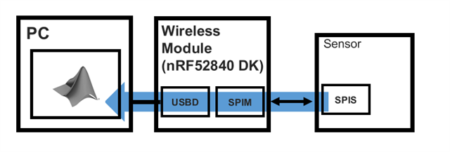
My goal: communicate with the ADC via SPIM and transmit the collected data via USBD
To briefly explain my code, the SPIM turns on and off at regular intervals(TIME_TO_WAIT_US) using a timer. The USBD sends data through a while loop.
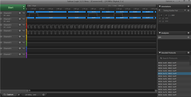
In the communication between the sensor and the wireless module (nRF52840 DK), the following applies:
- MOSI: The wireless module sends commands to the sensor.
- MISO: The sensor outputs results in response to the command
<My issue>
For debugging, I sent specific commands to the sensor, and upon checking the MATLAB workspace via USBD, I discovered data loss. Based on the following observations, I concluded that there might be a conflict between the uart_thread and spim_handler, though the exact cause of the conflict remains unclear:
1) When only USBD is running, there is no data loss issue.
2) When I increase TIME_TO_WAIT_US (which sets the cycle for repeating SPIM communication) to 100, the data loss disappears.
<ideal result>
In one period, '0020' should be output 16 times consecutively, and '0001' should be output twice consecutively.
'0020'
'0020'
'0020'
'0020'
'0020'
'0020'
'0020'
'0020'
'0020'
'0020'
'0020'
'0020'
'0020'
'0020'
'0020'
'0020'
'0001'
'0001'
'0020'
'0020'
'0020'
'0020'
'0020'
'0020'
'0020'
'0020'
'0020'
'0020'
'0020'
'0020'
'0020'
'0020'
'0020'
'0020'
'0001'
'0001'
... repetition
<Debugging result>
The sequence '0001' should appear twice in a row, but sometimes it appears three times consecutively. Additionally, the sequence '0020' is supposed to appear 16 times, but occasionally only 15 instances appear.
'0020'
'0020'
'0020'
'0020'
'0020'
'0020'
'0020'
'0020'
'0020'
'0020'
'0020'
'0020'
'0020'
'0020'
'0020'
'0020'
'0001'
'0001'
'0001'
...
'0020'
'0020'
'0020'
'0020'
'0020'
'0020'
'0020'
'0020'
'0020'
'0020'
'0020'
'0020'
'0020'
'0020'
'0020'
'0020'
'0001'
'0001'
'0001'
<Main code>#define PRIORITY 7
/**************** SPIM ****************/
#define MISO_PIN_MASTER 29
#define MOSI_PIN_MASTER 28
#define SCK_PIN_MASTER 4
#define SS_PIN_MASTER 3
//#define SPIM_INST_IDX 1
#define SPIM_INST_IDX 3
#define TIMER_INST_IDX 1
#define GPIOTE_INST_IDX 0
nrfx_spim_t spim1_inst = NRFX_SPIM_INSTANCE(SPIM_INST_IDX);
nrfx_timer_t timer1_inst = NRFX_TIMER_INSTANCE(TIMER_INST_IDX);
nrfx_gpiote_t gpiote_inst = NRFX_GPIOTE_INSTANCE(GPIOTE_INST_IDX);
nrf_ppi_channel_t ppi_channel_spi_start;
nrf_ppi_channel_t ppi_channel_spi_end;
volatile uint16_t initialization_counter = 0;
volatile uint16_t repeat_counter = 0;
volatile bool initialization_stop = false;
#define TIME_TO_WAIT_US 45
#define ROUND(x) ((x) >= 0 ? (long)((x) + 0.5) : (long)((x) - 0.5))
#define total_sampling_rate ROUND(1000000.0 / TIME_TO_WAIT_US)
#define N_Channel 16
#define N_Aux_command 2
#define per_ch_SAMPLE_RATE (total_sampling_rate /(N_Channel + N_Aux_command))
double lower_bandwidth = 1;
int upper_bandwidth = 300;
uint16_t registers[18];
RHDConfigParameters RHD_config;
RHDConfigParameters* RHD_p = &RHD_config;
uint8_t spim_tx_buf_initial[30][2];
uint8_t spim_tx_buf_repeat[18][2];
#define rx_data_size 244
uint8_t spim_rx_buf_A[rx_data_size][2];
uint8_t out_channel;
//////////////////////////////////////////////////
static struct fifo_data_t {
void *fifo_reserved; // This must be the first element for FIFO
uint8_t data[122][2]; // Buffer to hold the data
uint16_t len; // Length of the data
};
K_FIFO_DEFINE(uart_fifo);
struct fifo_data_t *spim_buf = NULL;
static volatile uint16_t buffer_index = 0;
const struct device *usbd_dev = DEVICE_DT_GET_ONE(zephyr_cdc_acm_uart);
void spim1_handler(nrfx_spim_evt_t const * p_event, void * p_context) {
if (spim_buf == NULL) {
spim_buf = k_malloc(sizeof(struct fifo_data_t));
if (spim_buf == NULL) {
LOG_ERR("Failed to allocate memory for FIFO buffer:%d", buffer_index);
return;
}
spim_buf->len = 0;
}
memcpy(spim_buf->data[buffer_index], spim_rx_buf_A[buffer_index], 2);
buffer_index++;
spim_buf->len++;
if (!initialization_stop) {
initialization_counter++;
if (initialization_counter == 30) {
initialization_stop = true;
spim1_inst.p_reg->TXD.PTR = (uint32_t)spim_tx_buf_repeat[0];
}
return;
}
if (buffer_index >= 120){ //if (buffer_index >= 100 && repeat_counter % 18 == 0){
k_fifo_put(&uart_fifo, spim_buf);
spim1_inst.p_reg->RXD.PTR = (uint32_t)spim_rx_buf_A[0];
buffer_index = 0;
spim_buf = NULL;
}
repeat_counter++;
if (repeat_counter % 18 == 0) {
spim1_inst.p_reg->TXD.PTR = (uint32_t)spim_tx_buf_repeat[0];
repeat_counter = 0;
}
}
void peripheral_setup(void){
nrfx_err_t error;
(void)error;
/* GPIOTE Setting */
static const nrfx_gpiote_output_config_t output_config = {
.drive = NRF_GPIO_PIN_S0S1,
.input_connect = NRF_GPIO_PIN_INPUT_DISCONNECT,
.pull = NRF_GPIO_PIN_NOPULL,
};
const nrfx_gpiote_task_config_t task_config = {
.task_ch = out_channel,
.polarity = NRF_GPIOTE_POLARITY_TOGGLE,
.init_val = NRF_GPIOTE_INITIAL_VALUE_HIGH,
};
error = nrfx_gpiote_output_configure(&gpiote_inst, SS_PIN_MASTER, &output_config, &task_config);
nrfx_gpiote_out_task_enable(&gpiote_inst, SS_PIN_MASTER);
/* SPIM 1 Setting */
nrfx_spim_config_t spim1_config = NRFX_SPIM_DEFAULT_CONFIG(SCK_PIN_MASTER,
MOSI_PIN_MASTER,
MISO_PIN_MASTER,
NRF_SPIM_PIN_NOT_CONNECTED);
spim1_config.frequency = NRFX_MHZ_TO_HZ(16);
// spim1_config.frequency = NRFX_MHZ_TO_HZ(8);
error = nrfx_spim_init(&spim1_inst, &spim1_config, spim1_handler,0);
nrfx_spim_xfer_desc_t spim1_xfer_desc = NRFX_SPIM_XFER_TRX((uint8_t*)spim_tx_buf_initial, 2, (uint8_t*)spim_rx_buf_A, 2);
uint32_t spim1_flags = NRFX_SPIM_FLAG_HOLD_XFER | NRFX_SPIM_FLAG_REPEATED_XFER;
error = nrfx_spim_xfer(&spim1_inst, &spim1_xfer_desc, spim1_flags);
spim1_inst.p_reg->TXD.PTR = (uint32_t)spim_tx_buf_initial[0];
spim1_inst.p_reg->TXD.MAXCNT = 2;
spim1_inst.p_reg->TXD.LIST =SPIM_TXD_LIST_LIST_ArrayList << SPIM_TXD_LIST_LIST_Pos;
spim1_inst.p_reg->RXD.PTR = (uint32_t)spim_rx_buf_A[0];
spim1_inst.p_reg->RXD.MAXCNT = 2;
spim1_inst.p_reg->RXD.LIST = SPIM_RXD_LIST_LIST_ArrayList << SPIM_RXD_LIST_LIST_Pos;
/* TIMER 0 Setting */
nrfx_timer_config_t timer0_config = NRFX_TIMER_DEFAULT_CONFIG(16000000);
timer0_config.bit_width = NRF_TIMER_BIT_WIDTH_32,
error = nrfx_timer_init(&timer1_inst, &timer0_config, timer0_handler);
//error = nrfx_timer_init(&timer1_inst, &timer0_config, NULL);
nrfx_timer_clear(&timer1_inst);
k_sleep(K_MSEC(2000));
uint32_t desired_ticks = nrfx_timer_us_to_ticks(&timer1_inst, TIME_TO_WAIT_US);
nrfx_timer_extended_compare(&timer1_inst, NRF_TIMER_CC_CHANNEL0, desired_ticks, NRF_TIMER_SHORT_COMPARE0_CLEAR_MASK, true);
/* PPI Setting */
uint32_t gpiote_task_addr = nrfx_gpiote_out_task_address_get(&gpiote_inst ,SS_PIN_MASTER);
uint32_t timer_start_compare_event_addr = nrfx_timer_compare_event_address_get(&timer1_inst, NRF_TIMER_CC_CHANNEL0);
uint32_t spi_start_task_addr = nrfx_spim_start_task_address_get(&spim1_inst);
uint32_t spi_end_evt_addr = nrfx_spim_end_event_address_get(&spim1_inst);
// Timer reaches the desired tick -> GPIOTE toggle(off), SPI start
error = nrfx_gppi_channel_alloc(&ppi_channel_spi_start);
nrfx_gppi_channel_endpoints_setup(ppi_channel_spi_start, timer_start_compare_event_addr, gpiote_task_addr);
nrfx_gppi_fork_endpoint_setup(ppi_channel_spi_start, spi_start_task_addr);
// SPI tx-rx transmission ends -> GPIOTE toggle(on)
error = nrfx_gppi_channel_alloc(&ppi_channel_spi_end);
nrfx_gppi_channel_endpoints_setup(ppi_channel_spi_end, spi_end_evt_addr, gpiote_task_addr);
}
void uart_thread_d(void){
struct fifo_data_t *uart_buf;
int send_len;
int inddex=0;
LOG_WRN("Starting uart_thread_d");
while (1) {
uart_buf = k_fifo_get(&uart_fifo, K_FOREVER);
send_len = uart_fifo_fill(usbd_dev, (uint8_t *)uart_buf->data, 2*(uart_buf->len));
k_free(uart_buf);
}
}
K_THREAD_DEFINE(uart_thread, 8192, uart_thread_d, NULL, NULL, NULL, PRIORITY, 0, 0);