Hi,
I'm trying to run the i2s output sample from NRF Connect SDK 2.7.0 on the nrf52840 DK, and I'm only getting the clock signal from P1.15, and no signal from any of the other lines (SDIN, SDOUT, LRCK).
My code is basically unmodified from the sample:
/*
 * Copyright 2023 NXP
 *
 * SPDX-License-Identifier: Apache-2.0
 */

#include <stdio.h>
#include <zephyr/kernel.h>
#include <zephyr/drivers/i2s.h>
#include <zephyr/sys/iterable_sections.h>

#define SAMPLE_NO 64

/* The data represent a sine wave */
static int16_t data[SAMPLE_NO] = {
	  3211,   6392,   9511,  12539,  15446,  18204,  20787,  23169,
	 25329,  27244,  28897,  30272,  31356,  32137,  32609,  32767,
	 32609,  32137,  31356,  30272,  28897,  27244,  25329,  23169,
	 20787,  18204,  15446,  12539,   9511,   6392,   3211,      0,
	 -3212,  -6393,  -9512, -12540, -15447, -18205, -20788, -23170,
	-25330, -27245, -28898, -30273, -31357, -32138, -32610, -32767,
	-32610, -32138, -31357, -30273, -28898, -27245, -25330, -23170,
	-20788, -18205, -15447, -12540,  -9512,  -6393,  -3212,     -1,
};

/* Fill buffer with sine wave on left channel, and sine wave shifted by
 * 90 degrees on right channel. "att" represents a power of two to attenuate
 * the samples by
 */
static void fill_buf(int16_t *tx_block, int att)
{
	int r_idx;

	for (int i = 0; i < SAMPLE_NO; i++) {
		/* Left channel is sine wave */
		tx_block[2 * i] = data[i] / (1 << att);
		/* Right channel is same sine wave, shifted by 90 degrees */
		r_idx = (i + (ARRAY_SIZE(data) / 4)) % ARRAY_SIZE(data);
		tx_block[2 * i + 1] = data[r_idx] / (1 << att);
	}
}

#define NUM_BLOCKS 20no data output
	#define MEM_SLAB_CACHE_ATTR __nocache
#else
	#define MEM_SLAB_CACHE_ATTR
#endif /* CONFIG_NOCACHE_MEMORY */

static char MEM_SLAB_CACHE_ATTR __aligned(WB_UP(32))
	_k_mem_slab_buf_tx_0_mem_slab[(NUM_BLOCKS) * WB_UP(BLOCK_SIZE)];

static STRUCT_SECTION_ITERABLE(k_mem_slab, tx_0_mem_slab) =
	Z_MEM_SLAB_INITIALIZER(tx_0_mem_slab, _k_mem_slab_buf_tx_0_mem_slab,
				WB_UP(BLOCK_SIZE), NUM_BLOCKS);

int main(void)
{
	void *tx_block[NUM_BLOCKS];
	struct i2s_config i2s_cfg;
	int ret;
	uint32_t tx_idx;
	const struct device *dev_i2s = DEVICE_DT_GET(DT_NODELABEL(i2s_tx));

	if (!device_is_ready(dev_i2s)) {
		printf("I2S device not ready\n");
		return -ENODEV;
	}
	/* Configure I2S stream */
	i2s_cfg.word_size = 16U;
	i2s_cfg.channels = 2U;
	i2s_cfg.format = I2S_FMT_DATA_FORMAT_I2S;
	i2s_cfg.frame_clk_freq = 44100;
	i2s_cfg.block_size = BLOCK_SIZE;
	i2s_cfg.timeout = 2000;
	/* Configure the Transmit port as Master */
	i2s_cfg.options = I2S_OPT_FRAME_CLK_MASTER
			| I2S_OPT_BIT_CLK_MASTER;
	i2s_cfg.mem_slab = &tx_0_mem_slab;
	ret = i2s_configure(dev_i2s, I2S_DIR_TX, &i2s_cfg);
	if (ret < 0) {
		printf("Failed to configure I2S stream\n");
		return ret;
	}

	/* Prepare all TX blocks */
	for (tx_idx = 0; tx_idx < NUM_BLOCKS; tx_idx++) {
		ret = k_mem_slab_alloc(&tx_0_mem_slab, &tx_block[tx_idx],
				       K_FOREVER);
		if (ret < 0) {
			printf("Failed to allocate TX block\n");
			return ret;
		}
		fill_buf((uint16_t *)tx_block[tx_idx], tx_idx % 3);
	}

	tx_idx = 0;
	/* Send first block */
	ret = i2s_write(dev_i2s, tx_block[tx_idx++], BLOCK_SIZE);
	if (ret < 0) {
		printf("Could not write TX buffer %d\n", tx_idx);
		return ret;
	}
	/* Trigger the I2S transmission */
	ret = i2s_trigger(dev_i2s, I2S_DIR_TX, I2S_TRIGGER_START);
	if (ret < 0) {
		printf("Could not trigger I2S tx\n");
		return ret;
	}

	for (; tx_idx < NUM_BLOCKS; ) {
		ret = i2s_write(dev_i2s, tx_block[tx_idx++], BLOCK_SIZE);
		if (ret < 0) {
			printf("Could not write TX buffer %d\n", tx_idx);
			return ret;
		}
	}
	/* Drain TX queue */
	ret = i2s_trigger(dev_i2s, I2S_DIR_TX, I2S_TRIGGER_DRAIN);
	if (ret < 0) {
		printf("Could not trigger I2S tx\n");
		return ret;
	}
	printf("All I2S blocks written\n");
	return 0;
}
The only change I did was change DEVICE_DT_GET(DT_ALIAS(i2s_tx)); to DEVICE_DT_GET(DT_NODELABEL(i2s_tx));
The only other change I did was add an app.overlay:
&pinctrl {
	i2s0_default_alt: i2s0_default_alt {
		group1 {
			psels = <NRF_PSEL(I2S_SCK_M, 1, 15)>,
				<NRF_PSEL(I2S_LRCK_M, 1, 12)>,
				<NRF_PSEL(I2S_SDOUT, 1, 13)>,
				<NRF_PSEL(I2S_SDIN, 1, 14)>;
		};
	};
};

i2s_tx: &i2s0 {
	status = "okay";
	pinctrl-0 = <&i2s0_default_alt>;
	pinctrl-names = "default";
};
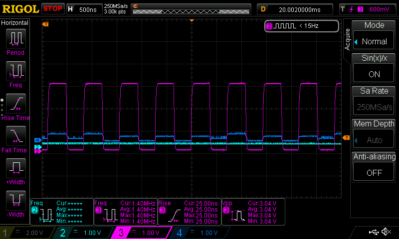
The pink signal is I2S_SCK, teal is SDOUT, blue is SDIN. With the exception of I2S_SCK the other signals are basically zero.