CoreHW ANT3 2x2 Antenna Array

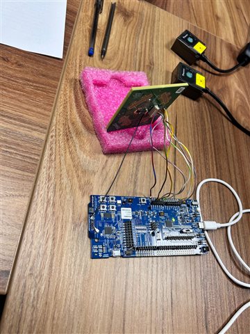
Hi, we have project AoA direction finding. Firstly we have nrf5340 dk kits. Also CoreHW ANT3 2x2 matrix antenna kit. I run the direction finding connectionless demo on nrf5340-dk. I did some changes on code. 

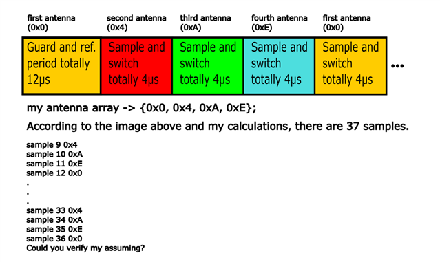
static const uint8_t ant_patterns[] = {0x0, 0x4, 0xA, 0xE}; -> this new array of the antenna matrix.
dfe-antenna-num = <4>; -> number of antenna.
and lastly I added this code into the cte_recv_cv function.
    for (int i = 0; i < report->sample_count; i++) {
            if (report->sample_type == BT_DF_IQ_SAMPLE_8_BITS_INT) {
                printf("IQ sample %d: I = %d, Q = %d, channel index = %d\n", i, report->sample[i].i, report->sample[i].q, my->ant_ids);
            }
    }
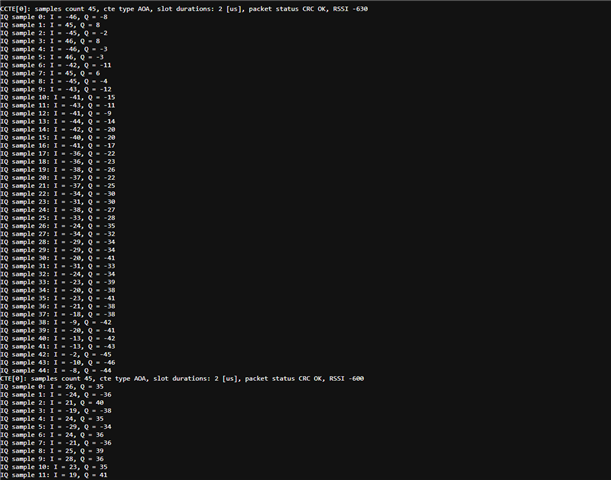
My serial output like this...
Q1: Am i configured right? Anything else for my antenna array.
Q2: I'm not sure this is normal  IQ datas. So I want know which pins active while scanning. For example 
CTE[0]: samples count 45, cte type AOA, slot durations: 2 [us], packet status CRC OK, RSSI -630, "first switch pin active".
I found some pins description in "radio_df.c" file but i couldnt access the pins. Do you help me how can i overcome this problem.
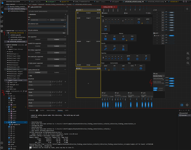
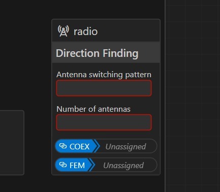
Q3: While i trying something on visual devicetree editor the screen shown below opened. But this were not on purpose so how can i access again this menu.
 
And my setup below 
  • Hi

    First off, from the image of your antenna it seems like you have soldered the antenna directly onto the PCB trace antenna of the nRF5340 DK. This is very likely to cause noise and it should only be connected from the J1 connector to the antenna array you're using. 

    1. From the snippet you have shared that seems correct, but I can't guarantee it's okay since I don't know what else you might have done in your project.

    2. I think this is raw IQ data which must be converted into vector form to be reviewed properly. We don't have have any specific sample code showing this, but you can check out this page for information on the various formulas used to translate IQ data between polar and rectangular form.

    3. So, when opening the nRF DeviceTree visual editor, you can go down to the NODES section an press the soc, that will open a visual representation of the nRF52833 SoC with a window for configuring the Direction Finding switching pattern and number of antennas. It will represent the values given in the nrf52833dk_nrf52833.overlay file here:

    &radio {
    	status = "okay";
    	/* This is a number of antennas that are available on antenna matrix
    	 * designed by Nordic. For more information see README.rst.
    	 */
    	dfe-antenna-num = <12>;
    	/* This is a setting that enables antenna 12 (in antenna matrix designed
    	 * by Nordic) for Rx PDU. For more information see README.rst.
    	 */
    	dfe-pdu-antenna = <0x0>;
    

    Best regards,

    Simon

  • Hi Simon, thank you for your advice and reply. Regarding your answers i'll make some changes. Please do not close the ticket. I'll get inform the here results. I think my answers may helpful the people.

  • Hi Simon, Long time I couldnt update the topic. Your answers very helpful to us. But we have one more questions. How many IQ data collect one time regarding the "direction_finding_connectionless_rx" samples and where this data collecting. Also we couldnt find radio seciton we want to observe the raw data of IQ. 


    Thank you. 

  • Hi

    As per the Direction Finding connectionless locator sample, the CTE length is 120µs and the switching slot is 1µs? Which will result in the following number of IQ samples (by default):

    • Eight samples from the reference period.

    • Switch-sample period duration is 120 µs - 12 µs = 108 µs. For the 1 µs antenna switching slot, the sample is taken every 2 µs (1 µs antenna switch slot, 1 µs sample slot). In this case, the number of samples from the switch-sample period is 108 µs / 2 µs = 54.

    What do you mean by "we couldn't find radio section we want to observe the raw data of IQ" exactly?

    Best regards,

    Simon

  • Hi Simonr, thank you for answer. I know this topic asking numerios time on devzone. But i just want to clearify the situtation. In my case I'm using 2µs slot. Regarding white paper in my case CTE length 160µs. Guard period and reference period totally 12µs. So 160µs-12µs = 148µs. After that i assuming that first antenna used in reference period so i'm starting the second antenna. Also 148µs/4=37 samples collected. I explain my assuming on image. Could you verify my assuming?


    Mentioned white paper: docs.nordicsemi.com/.../intro.html

Related