Cannot build I2S echo application for NRF5340

Hi, I am a beginner into the embedded audio space, and happened upon this board to use for our university project. Our team's current plan would be to produce audio directly on the board and play it through the headphone jack, but have not found much success with the NRF5340 Audio application, as it has a lot of integration with Bluetooth (which we don't need for now). Right now we just need a simple application that plays a tune on the board.

In my search I have found the I2S echo application, which seems like a simple start for our use case. However, when trying to build the application we encountered the following error:

-- Found BOARD.dts: C:/ncs/v2.6.2/zephyr/boards/arm/nrf5340_audio_dk_nrf5340/nrf5340_audio_dk_nrf5340_cpuapp.dts
-- Found devicetree overlay: boards/nrf5340dk_nrf5340_cpuapp.overlay
devicetree error: pinctrl-names property in /soc/peripheral@50000000/i2s@28000 in C:/ncs/v2.6.2/zephyr/misc/empty_file.c has 1 strings, expected 2 strings

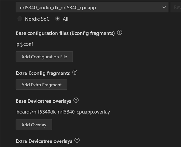
This is our build configuration (all other options left as default):
SDK version:

Any help would be appreciated! Thanks!

Parents
  • I received your friend request relating to this problem, and while I wish I could help, my previous post that you referenced is all the knowledge I have to share.

    I've spent two years so far studying Zephyr and NCS, and I'm still barely a beginner. Nordic's nrf5340_audio application remains an impenetrable maze to me, so inextricably intertwined that none of its modules can even be reused, and trying to dissect it for example code has been an exercise in frustration.

    Good luck, but I'm definitely not an expert to solicit for guidance.

  • Hi,

    To successfully build Zephyr I2S echo sample on the nrf5340_audio-dk board, you would need to make some modifications in your overlay file. You would need to have 2 pin control names and specify them in the pinctrl-names property for i2s in the overlay file. You can compare content of i2s0 in your overlay file with the i2s0 content nrf5340_audio_dk_nrf5340_cpuapp_common.dtsi file. Try to make the changes (shown below) in your overlay file and rebuild the application.

    i2s_rxtx: &i2s0 {
    	status = "okay";
    	pinctrl-0 = <&i2s0_default_alt>;
    	pinctrl-1 = <&i2s0_sleep>;
    	pinctrl-names = "default","sleep";
    	clock-source = "ACLK";
    };

    Best regards,
    Dejan

  • Hi,

    After successful flashing, you should be able to use Button 1 and Button 2 on the board as described in the I2S_echo sample documentation - "Press Button 1 to toggle the echo effect and Button 2 to stop the streams." What happens when you press Button 1 and Button 2?

    Best regards,
    Dejan

  • Hi, when I press the buttons I can see on the serial console stream/echo is toggled on/off, but I cannot hear anything over my headphones. 

  • I finally had the chance to gather something coherent enough to share that you might find informative.

    I've attached a simple example of the bare minimum code needed to initialize, configure, and enable the CS47L63 hardware codec, all in a single main.c file. It plays a sine wave using the I2S TX buffer, and then briefly mixes in the codec's tone and noise generators as well.

    It uses the CS47L63 driver verbatim from the nrf5340_audio sample, and demonstrates the basic steps necessary to reuse it in your own application. This example is liberally commented and extremely verbose, so should be easy to understand, and it uses readable constants instead of indecipherable hex whenever possible to help self document, which simplifies experimentation with other available codec features not included in this small demo.

    This code represents months of detailed study; I hope it helps.

    nrfadk_hello_codec.zip

  • Hi Johnny,

    I can't thank you enough for all the effort you put into this. This is the first time we've had success with the nRF5340 - no build errors and we can actually hear the output! With that said, we have a small question regarding adjusting the sampling rate. I noticed that in your code the calculation is stated as follows:

    /**
     * @brief	Initialize the CS47L63, start clocks, and configure subsystems.
     * 
     * @details	MCLK1 =  12,288,000 Hz  (I2S_CLKSRC.ACLK)
     * 		LRCLK =      48,000 Hz  (MCLK1 / I2S_CONFIG.RATIO)
     * 		BCLK =    1,536,000 Hz  (LRCLK * I2S_CONFIG.SWIDTH * 2)
     * 		FLL1 =   49,152,000 Hz  (MCLK1 * 4)
     * 		SYSCLK = 98,304,000 Hz  (FLL1 * 2)
     * 
     * @retval	`CS47L63_STATUS_OK`     The operation was successful.
     * @retval	`CS47L63_STATUS_FAIL`   Configuring the CS47L63 failed.
     * 
     * @warning	I2S MCLK1 must already be running before calling this function.
     * 
     */

    Where LRCKL (I presume is the sampling rate) is the master clock rate divided by the left-right clock ratio. For our application we require the sampling to be 16kHz - this means we need the left-right clock ratio to be I2S_CONFIG_RATIO_RATIO_768X without touching the master clock rate. However, upon looking at the macros files the ratio only goes up to 512X:

    /* Register: I2S_CONFIG_RATIO */
    /* Description: MCK / LRCK ratio */
    
    /* Bits 3..0 : MCK / LRCK ratio */
    #define I2S_CONFIG_RATIO_RATIO_Pos (0UL) /*!< Position of RATIO field. */
    #define I2S_CONFIG_RATIO_RATIO_Msk (0xFUL << I2S_CONFIG_RATIO_RATIO_Pos) /*!< Bit mask of RATIO field. */
    #define I2S_CONFIG_RATIO_RATIO_32X (0UL) /*!< LRCK = MCK / 32 */
    #define I2S_CONFIG_RATIO_RATIO_48X (1UL) /*!< LRCK = MCK / 48 */
    #define I2S_CONFIG_RATIO_RATIO_64X (2UL) /*!< LRCK = MCK / 64 */
    #define I2S_CONFIG_RATIO_RATIO_96X (3UL) /*!< LRCK = MCK / 96 */
    #define I2S_CONFIG_RATIO_RATIO_128X (4UL) /*!< LRCK = MCK / 128 */
    #define I2S_CONFIG_RATIO_RATIO_192X (5UL) /*!< LRCK = MCK / 192 */
    #define I2S_CONFIG_RATIO_RATIO_256X (6UL) /*!< LRCK = MCK / 256 */
    #define I2S_CONFIG_RATIO_RATIO_384X (7UL) /*!< LRCK = MCK / 384 */
    #define I2S_CONFIG_RATIO_RATIO_512X (8UL) /*!< LRCK = MCK / 512 */

    Is there a work around for this? Again, your help has been absolutely invaluable, and I truly hope others will come across this sample when they are learning to work with the nRF5340. Tremendous thanks again!

  • This is literally the absolute pinnacle of my current knowledge at the moment. I haven't tried any other sample rates or bit depths, nor do I even know how to play anything longer than will fit in the I2S buffer, which is limited to about 1 second at 48kHz. Memslabs and continuous arrays are still on my reading list.

    My learning curve to this point has been painfully steep. Nordic's documentation seems to assume that programmers only need a syntax reference rather than any informative explanation, so my actual understanding of the details thus far is tentative at best.

    The LRCLK (Left Right clock) or WSCLK (Word Select clock) toggles high and low for each audio channel's transmission, and is indeed equivalent to the sample rate. I'm using the undivided (bypassed) nRF53 ACLK as the source to FLL1 via the MCLK1 input, which dictates all the other clock and sampling rates in the system. You'll likely have to divide ACLK (aka MCLK1) via the I2S registers, and then compensate by changing FLL1's configuration.

    Section 4.10 Clocking and Sample Rates in the CS47L63 datasheet has plenty of further details to study, and the cs47l63_fll_*() functions defined in cs47l63.h are invaluable for configuring the complicated FLLs.

    That should get you started, and I'm happy to hear you learned a little something from my effort.

Reply
  • This is literally the absolute pinnacle of my current knowledge at the moment. I haven't tried any other sample rates or bit depths, nor do I even know how to play anything longer than will fit in the I2S buffer, which is limited to about 1 second at 48kHz. Memslabs and continuous arrays are still on my reading list.

    My learning curve to this point has been painfully steep. Nordic's documentation seems to assume that programmers only need a syntax reference rather than any informative explanation, so my actual understanding of the details thus far is tentative at best.

    The LRCLK (Left Right clock) or WSCLK (Word Select clock) toggles high and low for each audio channel's transmission, and is indeed equivalent to the sample rate. I'm using the undivided (bypassed) nRF53 ACLK as the source to FLL1 via the MCLK1 input, which dictates all the other clock and sampling rates in the system. You'll likely have to divide ACLK (aka MCLK1) via the I2S registers, and then compensate by changing FLL1's configuration.

    Section 4.10 Clocking and Sample Rates in the CS47L63 datasheet has plenty of further details to study, and the cs47l63_fll_*() functions defined in cs47l63.h are invaluable for configuring the complicated FLLs.

    That should get you started, and I'm happy to hear you learned a little something from my effort.

Children
No Data
Related