Cannot build I2S echo application for NRF5340

Hi, I am a beginner into the embedded audio space, and happened upon this board to use for our university project. Our team's current plan would be to produce audio directly on the board and play it through the headphone jack, but have not found much success with the NRF5340 Audio application, as it has a lot of integration with Bluetooth (which we don't need for now). Right now we just need a simple application that plays a tune on the board.

In my search I have found the I2S echo application, which seems like a simple start for our use case. However, when trying to build the application we encountered the following error:

-- Found BOARD.dts: C:/ncs/v2.6.2/zephyr/boards/arm/nrf5340_audio_dk_nrf5340/nrf5340_audio_dk_nrf5340_cpuapp.dts
-- Found devicetree overlay: boards/nrf5340dk_nrf5340_cpuapp.overlay
devicetree error: pinctrl-names property in /soc/peripheral@50000000/i2s@28000 in C:/ncs/v2.6.2/zephyr/misc/empty_file.c has 1 strings, expected 2 strings

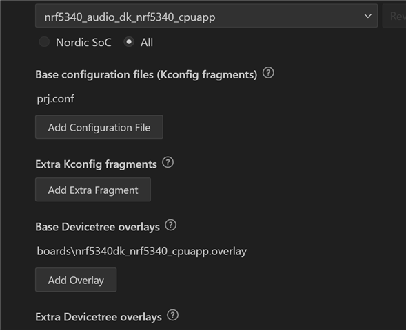
This is our build configuration (all other options left as default):
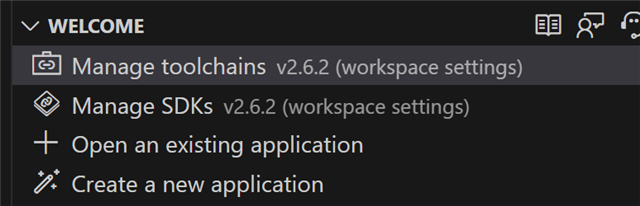
SDK version:

Any help would be appreciated! Thanks!

  • Hi Johnny,

    I can't thank you enough for all the effort you put into this. This is the first time we've had success with the nRF5340 - no build errors and we can actually hear the output! With that said, we have a small question regarding adjusting the sampling rate. I noticed that in your code the calculation is stated as follows:

    /**
     * @brief	Initialize the CS47L63, start clocks, and configure subsystems.
     * 
     * @details	MCLK1 =  12,288,000 Hz  (I2S_CLKSRC.ACLK)
     * 		LRCLK =      48,000 Hz  (MCLK1 / I2S_CONFIG.RATIO)
     * 		BCLK =    1,536,000 Hz  (LRCLK * I2S_CONFIG.SWIDTH * 2)
     * 		FLL1 =   49,152,000 Hz  (MCLK1 * 4)
     * 		SYSCLK = 98,304,000 Hz  (FLL1 * 2)
     * 
     * @retval	`CS47L63_STATUS_OK`     The operation was successful.
     * @retval	`CS47L63_STATUS_FAIL`   Configuring the CS47L63 failed.
     * 
     * @warning	I2S MCLK1 must already be running before calling this function.
     * 
     */

    Where LRCKL (I presume is the sampling rate) is the master clock rate divided by the left-right clock ratio. For our application we require the sampling to be 16kHz - this means we need the left-right clock ratio to be I2S_CONFIG_RATIO_RATIO_768X without touching the master clock rate. However, upon looking at the macros files the ratio only goes up to 512X:

    /* Register: I2S_CONFIG_RATIO */
    /* Description: MCK / LRCK ratio */
    
    /* Bits 3..0 : MCK / LRCK ratio */
    #define I2S_CONFIG_RATIO_RATIO_Pos (0UL) /*!< Position of RATIO field. */
    #define I2S_CONFIG_RATIO_RATIO_Msk (0xFUL << I2S_CONFIG_RATIO_RATIO_Pos) /*!< Bit mask of RATIO field. */
    #define I2S_CONFIG_RATIO_RATIO_32X (0UL) /*!< LRCK = MCK / 32 */
    #define I2S_CONFIG_RATIO_RATIO_48X (1UL) /*!< LRCK = MCK / 48 */
    #define I2S_CONFIG_RATIO_RATIO_64X (2UL) /*!< LRCK = MCK / 64 */
    #define I2S_CONFIG_RATIO_RATIO_96X (3UL) /*!< LRCK = MCK / 96 */
    #define I2S_CONFIG_RATIO_RATIO_128X (4UL) /*!< LRCK = MCK / 128 */
    #define I2S_CONFIG_RATIO_RATIO_192X (5UL) /*!< LRCK = MCK / 192 */
    #define I2S_CONFIG_RATIO_RATIO_256X (6UL) /*!< LRCK = MCK / 256 */
    #define I2S_CONFIG_RATIO_RATIO_384X (7UL) /*!< LRCK = MCK / 384 */
    #define I2S_CONFIG_RATIO_RATIO_512X (8UL) /*!< LRCK = MCK / 512 */

    Is there a work around for this? Again, your help has been absolutely invaluable, and I truly hope others will come across this sample when they are learning to work with the nRF5340. Tremendous thanks again!

  • Hi,

     Thank you for providing the sample. 

     , you could try to set your desired frequency using CONFIG_AUDIO_SAMPLE_RATE_16000_HZ=y and putting this KConfig option directly in your project configuration file.

    Best regards,
    Dejan

  • Hi   and  , I'm one of the developers of the audio application and I'm sorry to see that this is causing issues for you. This is a very big application that encompasses a lot of moving parts and some of these were written a long time ago. 

    To get a working I2S sample I would recommend taking our audio_i2s.c and header file together with the callback function here: i2s_block_complete_cb At the top of the I2S file you can see the ratios we use to get the different sample rates. The actual MCK frequency when using our driver is 6.144MHz, so that is why the ratio is half of what you would have used if the MCK was 12.288MHz.

    Looking at you code Johnny I spotted a bug in our code where we have mixed up 39845.888 (0x9BA6) with 39854 (0x9BAE) causing us to set the wrong value for the HFClock so thank you for that and sorry if that caused any confusion. It shouldn't cause much of an issue as this results in the LRClock running  1 Hz faster than expected to begin with but that would be corrected by drift compensation later on. I have opened a PR for fixing it though.

    In this function you can remove everything except the `audio_i2s_set_next_buf(tx_buf, rx_buf);` this is where the buffers for the next frame is set. How you provide those buffers are up to you and depends on where you are sourcing your data from. To get something up and running quickly you could use the `alt_buffer_get()` function to provide empty buffers to start with.

    To explain quickly how the I2S driver works:

    • It can be initialized at boot up using the `audio_i2s_init()` function
    • Once ready to start sending audio, call `audio_i2s_start()` providing the first tx-buffer to transmit and a rx-buffer to contain data fetched, these two are the same size.
    • Once the data has been sent to the I2S-module it will call the callback, that can be registered using `audio_i2s_blk_comp_cb_register()`, to ask for a new tx and rx-buffer and this goes in a loop until `audio_i2s_stop()` is called. The interval of how often the callback is called depends on the size of the buffers provided.

    Hope this helped a bit.

    EDIT: This response is written just with the I2S in mind, not changing any settings on the CS47L63. THat can be done by adding a line in the spi-writing, setting CS47L63_SAMPLE_RATE1 to 0x12

  • The main reason is as you already mentioned that we can reach all our desired LRCLK with the ratio settings available. If you look at table 3-13 in the CS47L63 data sheet it also states that if you use MCLK as a source for SYSCLK it has to be either 6.144 MHz or 12.288 MHz. Given the selection of ratios we have available we went with 6.144 MHz to be able to support 16 kHz.

    As mentioned we are adjusting the audio PLL ever so slightly up and down to be able to achieve synchronization between the left and the right audio receiver, this is based on the needs of LE Audio.

    As for the 0x66666000, that is the result based on the calculation you showed above. If you don't do the flooring operation it will be 0x66666666, but with the flooring it will be 0x66666000.

Related