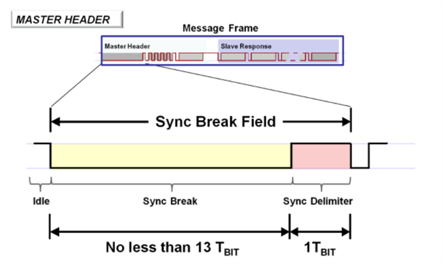
s this possible do LIN with NRF5340 (uart) hardware and software wise
s this possible do LIN with NRF5340 (uart) hardware and software wise
Hi Peter,
LIN bus isn't supported on the hardware on the nRF53. The software, I don't think we have anything.
There had been some questions in the past regarding this:
LIN-bus SW driver for nRF5x
Does the nRF51822 UART support LIN bus?
The NRF54 will support CAN bus, but I'm not so sure about LIN.
Hi Peter,
LIN bus isn't supported on the hardware on the nRF53. The software, I don't think we have anything.
There had been some questions in the past regarding this:
LIN-bus SW driver for nRF5x
Does the nRF51822 UART support LIN bus?
The NRF54 will support CAN bus, but I'm not so sure about LIN.
Lin bus uart requirements:
normal data bytes in lin are 8 bits with start and stop as normal uart comm.
The bitrate is max 20kbit.
The sync break field is the one that is not like normal uart comm.
its a SYNC BREAK of min 13 bit (low) followed by
a SYNC DELIMITER (High)
Is this not possible with nrf5340 uart ?
If not can it be done in another way with a timer/capture/compare or so?

Hi Peter,
I checked around internally but I don't think we have done any study on this. The UART driver in Zephyr is quite non-flexible that you can't really use a TIMER to access the pin when it's already assigned to UART peripheral.
It should be possible with big banging (use a timer as you said) for the SYNC BREAK but you will have to skip the default driver.
For specific timing like this it is possible to adjust the baud rate for the break-sync-identifier sequence (a pain with Zephyr) or better just don't use the Uart Tx function at all but instead use a PWM to drive the Uart Tx pin. Zephyr then just handles the Uart Rx pin at the specific baud rate. Both PWM and Uart use the same clock source, so crystal or not is not an issue as the slave adjusts its timing with the 0x55 sync field. The PWM Tx can be simply handled with nrfx. If needed I can share an example on the nRF52 series, not sure how easy it is to port to the nRF53.
As an aside, using PWM for the Tx makes differential signaling - which improves both range and noise-immunity - trivial. Using timers instead of Uart for the Rx allows differential Rx as well; the baud rate is usually low.
Thank you very much - for your valued input.
Yes i will be very interested for an example :-)
Here are a couple of replies I made which include using PWM for Tx:
Here's a 2-byte 10-bit frame; any number of bits can be used simply by changing the table:
// Example using grouped, note uses pin channels 0 and 2 not 0 and 1
nrf_pwm_values_grouped_t halfDuplexUartMsg[] = {
  //   Index   Normal pin 0        Inverted pin 2
  //   =====   =================== ==============
  { /* 0:0  */ 0x8000|(BIT_LOW),   (BIT_LOW),  }, // Start bit
  { /* 0:1  */ 0x8000|(STX_BIT_0), (STX_BIT_0) },
  { /* 0:2  */ 0x8000|(STX_BIT_1), (STX_BIT_1) },
  { /* 0:3  */ 0x8000|(STX_BIT_2), (STX_BIT_2) },
  { /* 0:4  */ 0x8000|(STX_BIT_3), (STX_BIT_3) },
  { /* 0:5  */ 0x8000|(STX_BIT_4), (STX_BIT_4) },
  { /* 0:6  */ 0x8000|(STX_BIT_5), (STX_BIT_5) },
  { /* 0:7  */ 0x8000|(STX_BIT_6), (STX_BIT_6) },
  { /* 0:8  */ 0x8000|(STX_BIT_7), (STX_BIT_7) },
  { /* 0:9  */ 0x8000|(BIT_HIGH),  (BIT_HIGH), }, // Stop bit 1

  { /* 1:0  */ 0x8000|(BIT_LOW),   (BIT_LOW),  }, // Start bit
  { /* 1:1  */ 0x8000|(ETX_BIT_0), (ETX_BIT_0) },
  { /* 1:2  */ 0x8000|(ETX_BIT_1), (ETX_BIT_1) },
  { /* 1:3  */ 0x8000|(ETX_BIT_2), (ETX_BIT_2) },
  { /* 1:4  */ 0x8000|(ETX_BIT_3), (ETX_BIT_3) },
  { /* 1:5  */ 0x8000|(ETX_BIT_4), (ETX_BIT_4) },
  { /* 1:6  */ 0x8000|(ETX_BIT_5), (ETX_BIT_5) },
  { /* 1:7  */ 0x8000|(ETX_BIT_6), (ETX_BIT_6) },
  { /* 1:8  */ 0x8000|(ETX_BIT_7), (ETX_BIT_7) },
  { /* 1:9  */ 0x8000|(BIT_HIGH),  (BIT_HIGH), }, // Stop bit 1
};
Sample encoding, normal or Manchester:
#define BIT_LOW               0           // Normal encoding
#define BIT_HIGH    (COUNTER_TOP)         // Normal encoding
//#define BIT_LOW   ((2*COUNTER_TOP)/3)   // Manchester encoding 2/3 bit
//#define BIT_HIGH  (COUNTER_TOP/3)       // Manchester encoding 1/3 bit
#define PWM_NEG (PIN_FEATHER_D6)          // Low level outside transmission
#define PWM_POS (PIN_FEATHER_D9)          // High level outside transmission
#define STX_BYTE 0x02 // Example start character: STX (^B)
#define ETX_BYTE 0x03 // Example start character: ETX (^C)

// Example STX byte in little-endian format
#define STX_BIT_0 (((STX_BYTE>>0) & 0x01) ? BIT_HIGH : BIT_LOW)
#define STX_BIT_1 (((STX_BYTE>>1) & 0x01) ? BIT_HIGH : BIT_LOW)
#define STX_BIT_2 (((STX_BYTE>>2) & 0x01) ? BIT_HIGH : BIT_LOW)
#define STX_BIT_3 (((STX_BYTE>>3) & 0x01) ? BIT_HIGH : BIT_LOW)
#define STX_BIT_4 (((STX_BYTE>>4) & 0x01) ? BIT_HIGH : BIT_LOW)
#define STX_BIT_5 (((STX_BYTE>>5) & 0x01) ? BIT_HIGH : BIT_LOW)
#define STX_BIT_6 (((STX_BYTE>>6) & 0x01) ? BIT_HIGH : BIT_LOW)
#define STX_BIT_7 (((STX_BYTE>>7) & 0x01) ? BIT_HIGH : BIT_LOW)
// Example ETX byte in little-endian format
#define ETX_BIT_0 (((ETX_BYTE>>0) & 0x01) ? BIT_HIGH : BIT_LOW)
#define ETX_BIT_1 (((ETX_BYTE>>1) & 0x01) ? BIT_HIGH : BIT_LOW)
#define ETX_BIT_2 (((ETX_BYTE>>2) & 0x01) ? BIT_HIGH : BIT_LOW)
#define ETX_BIT_3 (((ETX_BYTE>>3) & 0x01) ? BIT_HIGH : BIT_LOW)
#define ETX_BIT_4 (((ETX_BYTE>>4) & 0x01) ? BIT_HIGH : BIT_LOW)
#define ETX_BIT_5 (((ETX_BYTE>>5) & 0x01) ? BIT_HIGH : BIT_LOW)
#define ETX_BIT_6 (((ETX_BYTE>>6) & 0x01) ? BIT_HIGH : BIT_LOW)
#define ETX_BIT_7 (((ETX_BYTE>>7) & 0x01) ? BIT_HIGH : BIT_LOW)