nrf52840 DK for nrf52811 development

Hi, I am actually newbie to embedded system. 

My question is how can I upload my code to MCU.

There are very good tutorial about developing with development kit. 

So I successfully testing Bluetooth communication, gpio things. 

My next question is how can I upload a code to nrf52811 with nrf52840 DK board. 

I see that nrf52840 DK has a debug out pin(p18-10pin layout). and if I found correctly, it should connect with nrf52811's (vcc, gnd, swdclk, swdio pin - total 4 pin). 

Is it right that I have to find 10 pin to 4 pin cable and connect both DK and nrf52811.

And after I connect both how can I upload the programfile? Does segger embedded studio automatically recognize the nrf52811 mcu even though i connect DK with my computer via 5 pin - USB A cable? I just need to click target - connect jlink button in SES program same as I done at DK board?

So the connection is (computer) - 5pin - (DK) - 10pin to 4pin(?) - nrf52811. is it right...?

Sry for my basic question. But it would be very helpful for me starting my first embedded project!

Also I would be very grateful if you could provide specific websites or YouTube links that explain this process in detail.

Thank You so much 

Parents
  • Hello,

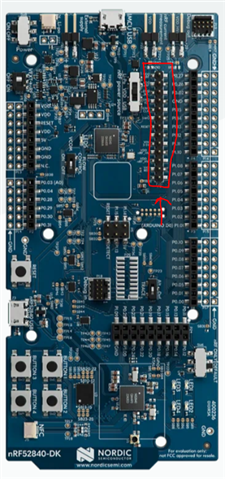
    The nRF52840 DK has two methods of programming external targets. One is the 10 pin DEBUG OUT port (P19) in the upper left corner. This is useful if your custom board has a 10 pin connector, which it sounds like your custom board doesn't have. The other way is to use P20, which is the long strip of GPIOs:

    which does more or less the same thing.

    So the way that both of these work is that when you connect your debugger on the DK to your computer, it will check if an external device is connected to either P19 or P20. If it detects anything, it will use that port instead of programming the nRF52840 on the DK. This goes for both debugging and programming. So in your case, it sounds like you should use P20. Depending on what version of the DK you have (it should say on the large white sticker, in addition to the serial number of the debugger), the name of the pins on P20 may be a little different. The thing is that you don't power the custom board via P20. 

    On the newer versions of the DK, this is described here:

    https://docs.nordicsemi.com/bundle/ug_nrf52840_dk/page/UG/dk/hw_debug_out.html

    But the same documentation for the nRF5340DK has an image, that is handy as well:

    https://docs.nordicsemi.com/bundle/ug_nrf5340_dk/page/UG/dk/ext_programming_support_P20.html

    The debug out part is the same on both the nRF52840DK and the nRF5340DK.

    So basically, you need to connect:

    DK -> Custom board

    SWDIO -> SWDIO

    SWDCLK ->  SWDCLK

    "GND Detect" (may not be named on the PCB, but same position) -> GND

    SWD_Sel / VTG -> VDD

    Note that SWD_Sel and GND detect does not power the external board, so you need to either power it externally (if so, make sure they have common ground, by shorting GND on DK to GND on custom board), or you can power it from VDD and GND on your DK (outside P20).

    Let me know if it doesn't work.

    Best regards,

    Edvin

Reply
  • Hello,

    The nRF52840 DK has two methods of programming external targets. One is the 10 pin DEBUG OUT port (P19) in the upper left corner. This is useful if your custom board has a 10 pin connector, which it sounds like your custom board doesn't have. The other way is to use P20, which is the long strip of GPIOs:

    which does more or less the same thing.

    So the way that both of these work is that when you connect your debugger on the DK to your computer, it will check if an external device is connected to either P19 or P20. If it detects anything, it will use that port instead of programming the nRF52840 on the DK. This goes for both debugging and programming. So in your case, it sounds like you should use P20. Depending on what version of the DK you have (it should say on the large white sticker, in addition to the serial number of the debugger), the name of the pins on P20 may be a little different. The thing is that you don't power the custom board via P20. 

    On the newer versions of the DK, this is described here:

    https://docs.nordicsemi.com/bundle/ug_nrf52840_dk/page/UG/dk/hw_debug_out.html

    But the same documentation for the nRF5340DK has an image, that is handy as well:

    https://docs.nordicsemi.com/bundle/ug_nrf5340_dk/page/UG/dk/ext_programming_support_P20.html

    The debug out part is the same on both the nRF52840DK and the nRF5340DK.

    So basically, you need to connect:

    DK -> Custom board

    SWDIO -> SWDIO

    SWDCLK ->  SWDCLK

    "GND Detect" (may not be named on the PCB, but same position) -> GND

    SWD_Sel / VTG -> VDD

    Note that SWD_Sel and GND detect does not power the external board, so you need to either power it externally (if so, make sure they have common ground, by shorting GND on DK to GND on custom board), or you can power it from VDD and GND on your DK (outside P20).

    Let me know if it doesn't work.

    Best regards,

    Edvin

Children
Related