
I have a device on my desk that performs the data transfer I need, so I know it's possible. I've attached a screenshot of the successful data transfer.
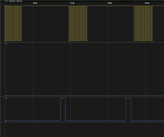
I tried to replicate the setup using a 2-byte buffer with PPI and Timer1. On the oscilloscope, the signals look similar, but I'm having issues processing the data. The SPI event handler (in this case) needs to be called every 2 microseconds to transfer data to a larger buffer.
Do you have any suggestions on how to approach this? Below is the code that transfers the data but loses all the data at the same time.
nrfx_err_t err_code;
    uint8_t ppi_channel1, ppi_channel2;

    nrfx_timer_t timer_inst = NRFX_TIMER_INSTANCE(1);
    timer1_init(&timer_inst);

    // Allocate PPI channels
    err_code = nrfx_gppi_channel_alloc(&ppi_channel1);
    if (err_code != NRFX_SUCCESS)
    {
        LOG_ERR("PPI channel allocation error for channel 1");
        return;
    }
    err_code = nrfx_gppi_channel_alloc(&ppi_channel2);
    if (err_code != NRFX_SUCCESS)
    {
        LOG_ERR("PPI channel allocation error for channel 2");
        return;
    }


    uint8_t task_channel;
    err_code = nrfx_gpiote_channel_alloc(&task_channel);
    if (err_code != NRFX_SUCCESS)
    {
        LOG_ERR("Channel alloc failed: %d", err_code);
        return;
    }

    nrfx_gpiote_output_config_t config = NRFX_GPIOTE_DEFAULT_OUTPUT_CONFIG;
    nrfx_gpiote_task_config_t task_config = {
        .task_ch = task_channel,
        .polarity = NRF_GPIOTE_POLARITY_TOGGLE,
        .init_val = NRF_GPIOTE_INITIAL_VALUE_HIGH
    };

    err_code = nrfx_gpiote_output_configure(ADC_CS_PIN, &config, &task_config);
    if (err_code != NRFX_SUCCESS)
    {
        LOG_ERR("Output configure failed: %d", err_code);
        return;
    }

    nrfx_gpiote_out_task_enable(ADC_CS_PIN);


    uint32_t timer_addr = nrfx_timer_compare_event_address_get(&timer_inst, NRF_TIMER_CC_CHANNEL0);
    uint32_t cs_set_addr = nrfx_gpiote_set_task_address_get(ADC_CS_PIN);
    uint32_t cs_clear_addr = nrfx_gpiote_clr_task_address_get(ADC_CS_PIN);
    uint32_t spim_end_event_addr = nrf_spim_event_address_get(spim_inst.p_reg, NRF_SPIM_EVENT_END);
    uint32_t spim_start_task_addr = nrf_spim_task_address_get(spim_inst.p_reg, NRF_SPIM_TASK_START);

    nrfx_gppi_channel_endpoints_setup(ppi_channel1, timer_addr, cs_clear_addr);
    nrfx_gppi_fork_endpoint_setup(ppi_channel1, spim_start_task_addr);
    nrfx_gppi_channel_endpoints_setup(ppi_channel2, spim_end_event_addr, cs_set_addr);

    err_code = nrfx_spim_xfer(&spim_inst, &xfer_desc, NRFX_SPIM_FLAG_HOLD_XFER| NRFX_SPIM_FLAG_REPEATED_XFER);
    if (err_code != NRFX_SUCCESS)
    {
        LOG_ERR("Initial SPI transfer failed: %d", err_code);
        return;
    }

