BLE fund. Lesson 4 exercise 3 - UART communication betewen nrf52840DK and nrf9161DK

Hi

I'm using the nrf52840DK and this example: "BLE Fundamentals, Lesson 4, Exercise 3," where you can send/receive strings between UART and Bluetooth. This works perfectly.

My mission is: Write a string on my phone -> receive it via Bluetooth on the nrf52840DK -> send the data via UART pins -> receive the data on the nrf9161 (UART).

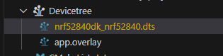
First things first, how can I reroute the nordic,nus-uart = &uart0; on the nrf52840DK to specific pins, if possible?

In the lesson description, it says that "nus" is a virtual serial port emulated over USB, so I’m guessing I can't change the pinout and need to create a new UART instance.

/ {
    chosen {
        zephyr,console = &cdc_acm_uart0;
        nordic,nus-uart = &cdc_acm_uart0;
    };

So to sum up my questions:

Is there any easy way to change the UART output, or do I need to create a new UART instance and modify main.c, as it calls many UART "nus" functions?

What i have tested so far:

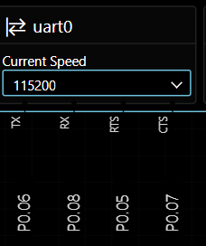
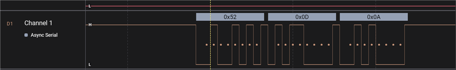
When typing "R" in the terminal i get a hex on the RX pin. P0.08 on the nrf52840, so that seems correct, but when sending from phone i dont get anything on any of the pins:

(on the terminal i get the correct string from the phone but not through the pins)

Thanks!

/Egil

  • Hello Egil,

    (on the terminal i get the correct string from the phone but not through the pins)

    When you send a message from the phone, it should be printed on the UARTs TX pin, P0.06. The fact that you see it in the terminal, means that it must have been sent out via P0.06. 

    However, if I understand your question correctly, you simply want to change what GPIOs that are being used by the UART, right?

    In a file called nrf52840dk_nrf52840-pinctrl.dtsi, located in ncs\zephyr\boards\nordic\nrf52840dk\nrf52840dk_nrf52840-pinctrl.dtsi, you should see something like this:

    
    	uart0_sleep: uart0_sleep {
    		group1 {
    			psels = <NRF_PSEL(UART_TX, 0, 6)>,
    				<NRF_PSEL(UART_RX, 0, 8)>,
    				<NRF_PSEL(UART_RTS, 0, 5)>,
    				<NRF_PSEL(UART_CTS, 0, 7)>;
    			low-power-enable;
    		};
    	};
    	...

    You can find it by using the device tree file in VS Code:

    locating uart0 anywhere in that file, and right click -> go to definition,

    So to configure devicetree functionality, you can copy whatever you want to change, and paste it into a file called <board_name>.overlay. So in your case, call it nrf52840dk_nrf52840.overlay, and place it in your application folder (the same folder containing your prj.conf). In it, you paste whatever you copied, and change whatever you want to change. So for example:

    &pinctrl {
    	uart0_default: uart0_default {
    		group1 {
    			psels = <NRF_PSEL(UART_TX, 0, 6)>,
    				<NRF_PSEL(UART_RTS, 0, 5)>;
    		};
    		group2 {
    			psels = <NRF_PSEL(UART_RX, 0, 8)>,
    				<NRF_PSEL(UART_CTS, 0, 7)>;
    			bias-pull-up;
    		};
    	};
    
    	uart0_sleep: uart0_sleep {
    		group1 {
    			psels = <NRF_PSEL(UART_TX, 0, 6)>,
    				<NRF_PSEL(UART_RX, 0, 8)>,
    				<NRF_PSEL(UART_RTS, 0, 5)>,
    				<NRF_PSEL(UART_CTS, 0, 7)>;
    			low-power-enable;
    		};
    	};
    };

    (note that I added the last bracked and semi colon: };

    Whatever changes you do in this overlay file will be used instead of the default .dts or .dtsi files, without changing the rest of the .dts files.

    You may need to delete your build configuration/build folder and create a new build configuration for the compiler to actually detect your .overlay file. 

    Best regards,

    Edvin

  • thx for the answer!
    It works! I also get the correct string on the logic analyzer from the TX from the nrf52840 (with bl to uart example).

    The problem is now that i have implemented the code below on the nrf9161 and connected TX (nrf52840) to RX (nrf9161):

    This code is supposed to receive a string through UART and it works for now by sending a string via the vscode terminal and it prints back that it received the string.

    So each nrf's works correct separately when testing.

    But when connecting both at the same time, they both get blocked, so now i dont get an response in the terminal from the nrf9161(UART receive) or when trying to send a string via BL via the phone on the nrf52840(BL->UART ex).

    what i have tried:

    * The logic analyzer does not pick up anything when both are connected.

    * I also tried it by connecting the nrf52840(BL->UART ex) to an external powerbank to see if it was something with my laptop not beeing able to take two nrf's but this gave same result.

    * Also i tried making a common gnd between them but same result.

    The code to receive UART data (nrf9161):

    #include <zephyr/kernel.h>

    #include <zephyr/device.h>

    #include <zephyr/devicetree.h>

    #include <zephyr/sys/printk.h>

    #include <zephyr/drivers/uart.h>

    #define SLEEP_TIME_MS   1000

    #define RECEIVE_BUFF_SIZE 1  // Buffer size of 1 for single-character reception

    #define RECEIVE_TIMEOUT 100

    /* Get the UART device pointer */

    const struct device *uart = DEVICE_DT_GET(DT_NODELABEL(uart0));

    static uint8_t rx_buf[RECEIVE_BUFF_SIZE] = {0};

    /* UART callback to handle received data */

    static void uart_cb(const struct device *dev, struct uart_event *evt, void *user_data) {

        switch (evt->type) {

            case UART_RX_RDY:

                // Print each received character immediately

                printk("%c", evt->data.rx.buf[evt->data.rx.offset]);  // Print the received character

                break;

            case UART_RX_DISABLED:

                // Re-enable UART RX in case it was disabled for any reason

                uart_rx_enable(dev, rx_buf, sizeof(rx_buf), RECEIVE_TIMEOUT);

                break;

            default:

                break;

        }

    }

    int main(void) {

        int ret;

        /* Verify UART device is ready */

        if (!device_is_ready(uart)) {

            printk("UART device not ready\n");

            return 1;

        }

        /* Register UART callback and enable receive */

        ret = uart_callback_set(uart, uart_cb, NULL);

        if (ret) {

            printk("Failed to set UART callback\n");

            return 1;

        }

        ret = uart_rx_enable(uart, rx_buf, sizeof(rx_buf), RECEIVE_TIMEOUT);  // Enable with buffer for continuous reception

        if (ret) {

            printk("Failed to enable UART RX\n");

            return 1;

        }

        printk("UART initialized. Waiting for data...\n");

        while (1) {

            k_msleep(SLEEP_TIME_MS);

        }

    }

  • Hmm... Perhaps flow control is enabled. Try connecting RTS on one device to CTS on the other. 

    To disable flow control, add this to your nrf52840dk_nrf52840.overlay, and your equivalent nRF91 overlay file in your nrf91 appilcation:

        /delete-property/ hw-flow-control;

    So your file should look something like this now:

    &uart0 {
    	compatible = "nordic,nrf-uarte";
    	status = "okay";
        /delete-property/ hw-flow-control;
    	current-speed = <115200>;
    	pinctrl-0 = <&uart0_default>;
    	pinctrl-1 = <&uart0_sleep>;
    	pinctrl-names = "default", "sleep";
    };
    
    &pinctrl {
    	uart0_default: uart0_default {
    		group1 {
    			psels = <NRF_PSEL(UART_TX, 0, 6)>,
    				<NRF_PSEL(UART_RTS, 0, 5)>;
    		};
    		group2 {
    			psels = <NRF_PSEL(UART_RX, 0, 8)>,
    				<NRF_PSEL(UART_CTS, 0, 7)>;
    			bias-pull-up;
    		};
    	};
    
    	uart0_sleep: uart0_sleep {
    		group1 {
    			psels = <NRF_PSEL(UART_TX, 0, 6)>,
    				<NRF_PSEL(UART_RX, 0, 8)>,
    				<NRF_PSEL(UART_RTS, 0, 5)>,
    				<NRF_PSEL(UART_CTS, 0, 7)>;
    			low-power-enable;
    		};
    	};
    };

    Let me know if it doesn't work.

    Best regards,

    Edvin

Related