nRF5340 LFCLK oscillator control clarification

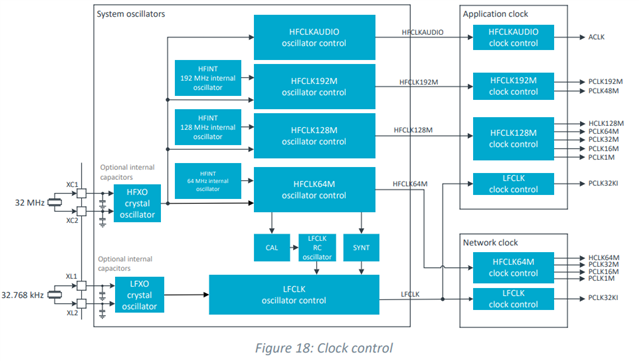
What is the exact LFCLK control behavior with regards to control from both the APPCORE and NETCORE?  The clock control figure at https://docs.nordicsemi.com/bundle/ps_nrf5340/page/chapters/clock/doc/clock.html shows one LFCLK feeding both the APPCORE and NETCORE LFCLK clock control.  Are the following true:

  • There is only one LFRC and LFSYNT in the system.
  • Both cores can request CAL of the LFRC but only one needs to.
  • If LFSYNT is requested by the APPCORE running an RTC, then the NETCORE PCLK32KI will be based on LFSYNT, regardless of NETCORE's LFCLKSRC setting.
  • If LFSYNT is requested by the NETCORE running an RTC, then the APPCORE PCLK32KI will be based on LFSYNT, regardless of APPCORE's LFCLKSRC setting.
  • LFCLKSTAT only returns the setting requested by the core, it does return what clock is sourcing LFCLK
    For example, if APPCORE LFCLKSRC=3 and NETCORE LFCLKSRC=2, NETCORE LFCLKSTAT SRC will equal 2, APPCORE LFCLKSTAT SRC will equal 3
  • In a typical NRF SDK system, the LFCLK is always going to be running because the RTC is used for the system tick.

Thank you, 

Dustin

Parents
  • Hi Dustin

    First off, I'm uploading this block diagram for reference:

    1. Referring to the block diagram above you can see that there is one LFCLK RC oscillator, and one LF synthesized clock in the system. So true.
    2. Any core can trigger the calibration task independently of the other, but a DONE event will be generated in both cores when complete. So true.
    3. If two instances of the LFCLK control system request different LFCLK sources, the power and clock subsystem will secure that the most accurate of the requested LFCLK sources is selected. If one instance requests a particular source to stop when another LFCLK control instance requests the ame source to run, but at a lower accuracy, the power and clock subsystem will switch to the less accurate source. So true.
    4. True, based on the previous paragraph.
    5. This returns an indication of what LF clock source is running. This register value in any CLOCK instance reflects status only due to configurations/actions in that CLOCK instance.
    6. Only if the RTC is enabled for the project/application this would be true. It's possible to not use the RTC at all.

    Best regards,

    Simon

Reply
  • Hi Dustin

    First off, I'm uploading this block diagram for reference:

    1. Referring to the block diagram above you can see that there is one LFCLK RC oscillator, and one LF synthesized clock in the system. So true.
    2. Any core can trigger the calibration task independently of the other, but a DONE event will be generated in both cores when complete. So true.
    3. If two instances of the LFCLK control system request different LFCLK sources, the power and clock subsystem will secure that the most accurate of the requested LFCLK sources is selected. If one instance requests a particular source to stop when another LFCLK control instance requests the ame source to run, but at a lower accuracy, the power and clock subsystem will switch to the less accurate source. So true.
    4. True, based on the previous paragraph.
    5. This returns an indication of what LF clock source is running. This register value in any CLOCK instance reflects status only due to configurations/actions in that CLOCK instance.
    6. Only if the RTC is enabled for the project/application this would be true. It's possible to not use the RTC at all.

    Best regards,

    Simon

Children
No Data
Related