Interact with nRF9151 using external third party MCU

Hello, guys Wave

We want to evaluate nRF9151 SiP the following way:

  • To set it to operate in serial mode in which it is ready to receive AT commands (it comes pre-flashed in that mode on nRF9151-DK, to the best of my understanding)
  • To send AT commands and other necessary GPIO control using some external MCU (not nRF5340 MCU which is populated on nRF9151-DK board but some third party, external MCU)

Few questions related to our goal:

  1. Is it possible to achieve what we want?
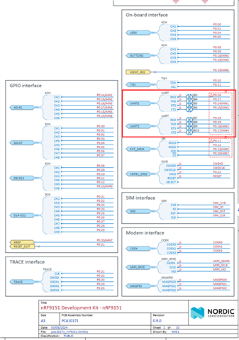
  2. Which UART interface should we use for sending AT commands - UART1 or UART2?
  3. In addition to UART Rx/Tx, do we need some other GPIO to control the modem (e.g. Reset, some other GPIO that plays a role in modem control...)?
  4. We would like to test NB-IoT modem by default and switch to LTE-M if needed. How to achieve this, is there any special AT command for switching between available modes (NB-IoT/LTE-M)?
Thanks in advance for your time and efforts. Looking forward to hearing from you.

Sincerely,
Bojan.

Parents
  • Okay, I figured out that UART1 can be used to control the modem by the external MCU through the pins P0.26 (Modem RX, MCU TX) and P0.27 (Modem TX, MCU RX). It also seems that pressing the RESET button on nRF9151-DK resets the modem.

    Is there any other pin of the modem that needs to be controlled by an external MCU in order to reboot/reset the modem if it gets stuck or to put it so sleep if we want?

  • Hello Bojan,

    I'll try to reply to you questions one by one.

    To set it to operate in serial mode in which it is ready to receive AT commands (it comes pre-flashed in that mode on nRF9151-DK, to the best of my understanding)

    I would recommend at least getting the nRF Connect for Desktop and running the Quick Start app. Also you may want to update the Modem FW and Serial LTE Modem application (you can do that with the Cellular Monitor app in nRF Connect for Desktop).

    If you want to for example switch the pins used for things, then you'd need to compile SLM by yourself.

    Is it possible to achieve what we want?

    Yes.

    Which UART interface should we use for sending AT commands - UART1 or UART2?

    I should probably explain one thing first: those are just the default pins for UARTx. On the nRF91 family you can freely choose which GPIO pins do you want to connect to for example UART.

    Markings "UART1" and "UART2" on the DK are just showing 2 default UART pinouts on the DK, while actually being connected to the UART0 and UART1 peripheral instances on the nRF9151 SiP.

    By default SLM will be using the pins marked as UART1 on the DK schematics (UART0 peripheral on nRF9151).

    Pins marked as UART2 are by default connected to the UART1 peripheral, which is used for modem traces by default and can be useful to have routed to some test points/connector even in your end product.

    In addition to UART Rx/Tx, do we need some other GPIO to control the modem (e.g. Reset, some other GPIO that plays a role in modem control...)?

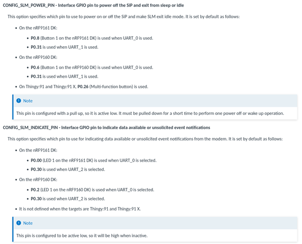
    Other than the aforementioned reset, if you look at configuration options there are two more pins that you can/should use, set by CONFIG_SLM_POWER_PIN and CONFIG_SLM_INDICATE_PIN:

    We would like to test NB-IoT modem by default and switch to LTE-M if needed. How to achieve this, is there any special AT command for switching between available modes (NB-IoT/LTE-M)?

    Please take a look at our DevAcademy course page explaining some of the basic AT commands:

    https://academy.nordicsemi.com/courses/cellular-iot-fundamentals/lessons/lesson-2-cellular-fundamentals/topic/lesson-2-at-commands/

    As shown there you can use the AT%XSYSTEMMODE command.

    Best regards,

    Michal

  • ... and if we don't want CMUX and PPP features to be implemented in SLM but to have SLM sample behaving as a simple modem that expects AT commands over UART, we would need to re-compile the SLM sample and exclude overlay-cmux.conf and overlay-ppp.conf files from compilation.

    Correct?

  • Those files have to be manually chosen to be used, so you shouldn't need to exclude them specifically.

  • I see the overlay-ppp-without-mux.conf/overlay files in SLM sample app, and I'm wondering what's the difference between PPP with and without CMUX. 

    Anyway, I was able to connect my external third party MCU to the customized SLM sample app and make it communicate with test-endpoint.com server. What I notice is that it's kind of a difficult/impossible for my external MCU to wake up the nRF9151 SiP running SLM app. That's why I used

    CONFIG_SLM_START_SLEEP=n

    flag to have the modem awake on start-up. What is actually needed on CONFIG_SLM_POWER_PIN in order to properly wake up the SLM modem? Toggling, pulse, something more...How do we need to configure the MCU's GPIO that will be used for waking up the SLM?

  •  , I found what's wrong with the GPIO of my external MCU that's connected to CONFIG_SLM_POWER_PIN. After fixing it, I was able to detect a proper 100ms wake up pulse on that GPIO. 

    Now, when I flash the version of SLM app with 

    CONFIG_SLM_START_SLEEP=y

    (modem sleeping on start up), cellular_modem sample running on my external MCU can't properly sync-up with SLM app. As you can see from below debug traces, here is what happens in infinite loop:

    1. Wake-up pulse is applied
    2. cellular_modem sample sends AT command
    3. SLM responds with `Ready`. cellular_modem sample treat this as unknown command
    4. cellular_modem goes to step 1 and sends Wake-up pulse again:

    Any help here?

Reply
  •  , I found what's wrong with the GPIO of my external MCU that's connected to CONFIG_SLM_POWER_PIN. After fixing it, I was able to detect a proper 100ms wake up pulse on that GPIO. 

    Now, when I flash the version of SLM app with 

    CONFIG_SLM_START_SLEEP=y

    (modem sleeping on start up), cellular_modem sample running on my external MCU can't properly sync-up with SLM app. As you can see from below debug traces, here is what happens in infinite loop:

    1. Wake-up pulse is applied
    2. cellular_modem sample sends AT command
    3. SLM responds with `Ready`. cellular_modem sample treat this as unknown command
    4. cellular_modem goes to step 1 and sends Wake-up pulse again:

    Any help here?

Children
Related