NRF52840 RF Wireless Tuning

Hi,

I have a design which mostly follows the reference designs.

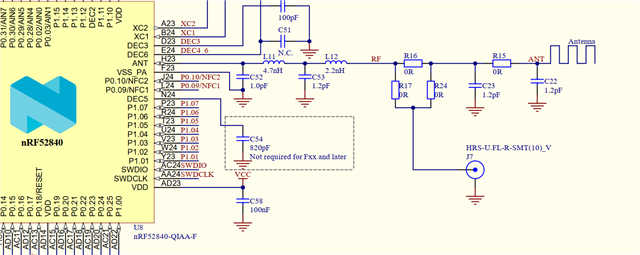
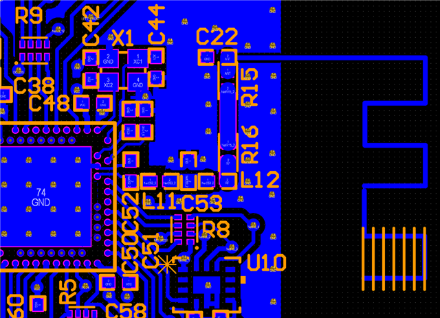
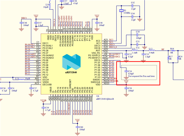
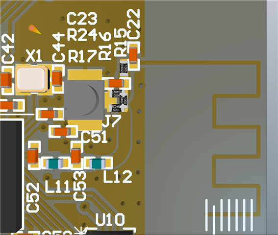
I've added a Resistor Network R16/17/24 to allow a UFL connector to connect to the ANT and isolate it from the NRF RF Output

I would like it if you can confirm if the process of tuning is correct.

  • R16,R17,R24,C22,C23 all removed to isolate
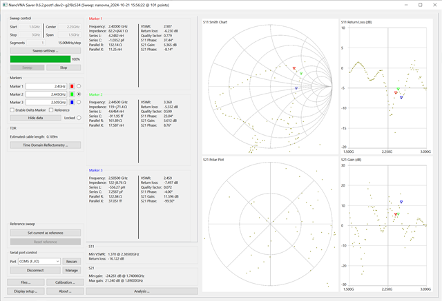
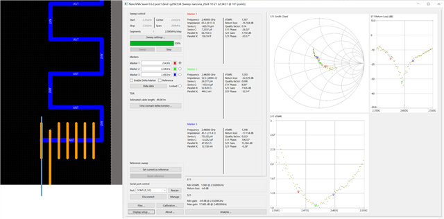
  • I have a VNA and set it to sweep from 1.5GHz to 3.0GHz.
  • Open - R16/R17/R24 all removed
  • Short - R24=0R, C23=0R, R15=Open
  • 50ohm Load - R24=0R, C23=50ohm R15=Open

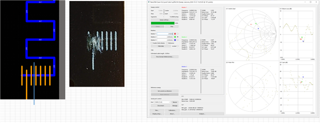
I do an initial sweep and see that the lowest loss needs to move up higher in frequency, so I cut some ANT track.

After cutting I see that the frequency has moved such that 2.44GHz is the lowest.

I then recalibrate over a Freq range of 2.35G -> 2.55G.

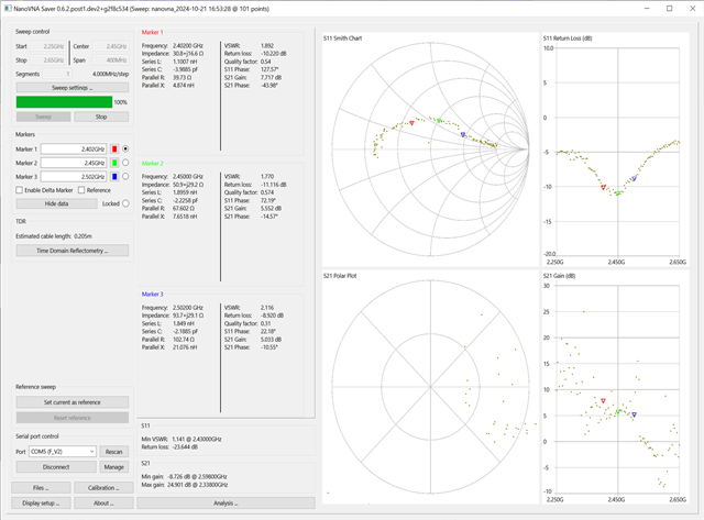
Then I populate some Matching Network values C23=3.0nH, R15=1.0pF, R24=0R, C22=Open

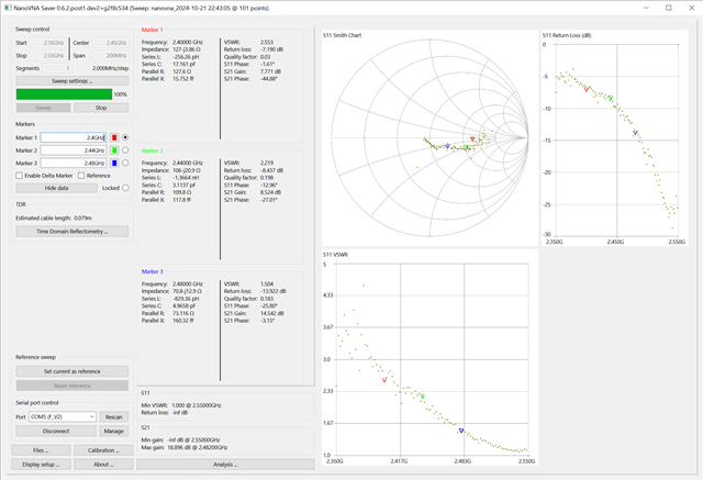
However it seems that I have cut too much ANT and then the frequency is too high.

So I then get a fresh board without ANT cuts, populate the same C23=3.0nH, R15=1.0pF, R24=0R, C22=Open and then cut again to minimise the return loss and confirm ANT length and matching values.

Could you please comment on this tuning process?

Thanks!

Parents
  • Hi,

    The tuning process and results looks good. Cutting down the antenna without any matching components mounted will usually lead to a shift in resonance frequency when mounting the components later.

    The only thing different I would have done, is to start with a 1pF capacitor mounted to C22, when cutting down the antenna, it may well be that you don't need any more components than just a shunt cap.


    Best regards,

    Bendik

  • Hi,

    Despite the results looking good, when I use a NRF52 Dongle and load the RSSI meter on, when reading the RSSI from another NRF52 dongle which is operating with the DTM firmware, the RSSI is about -66/-67dBm.

    Using the same DTM firmware on my board results in an RSSI of -89dBm at the same distance and frequency.

    Any ideas on what I should do here?

    Thanks!

  • Hi,

    This could indicate that the radio matching network needs to be tuned as well.

    Do you have access to a spectrum analyzer to measure the output power from the SoC?

    When tuning the radio matching network its best to use a spectrum analyzer to tune for maximum output power on the fundamental frequency and low harmonic distortion, rather than using a VNA and impedance.


    You could send us some samples of the board to check the radio performance, and tune the matching network, if you don't have the equipment needed. If this is something you would like us to do, please open a private ticket and share your schematic and PCB layout files.


    Best regards,

    Bendik

  • Hi Bendik,

    I have an antenna design like this, but I'm getting a very poor signal, what could this be due to? I wonder if it is due to the GND Pour that surrounds the Antenna. Any suggestions?

    Strangely enough, only a few of these boards exhibit the poor signal strength.

    When uploading some DTM software to it and testing it against the RSSI viewer, the problematic boards have a -90dBm signal at around 1mm distance.

    While a different board from the same batch will show -32dBm at 1mm and ~ -52dBm at a few metres, which seems decent.

    The problematic board shows the same resistance to ground at different points along the antenna as the other working boards. So far I tested 7 boards, and only 1 of them seems to have an issue with getting a strong output. I guess it might go down as a manufacturing defect, but I can't understand how or what the issue could be.

    I tried reflowing the filter components and the BGA area by the radio but it did not improve the results. All the boards look similar and there doesn't seem to be any obvious defects.

    Regards,

    Adrian

  • Hi Adrian,

    Apologies for the delay.

    The GND pour looks good, it is not too close to the antenna so it shouldn't affect it.

    Depending on the RF noise in your surrounding, -90dBm could be very close to the noise floor.

    Do you have any other way of verifying that the board is transmitting anything?

    It could be a issue with the 32MHz crystal not starting.


    Best regards,

    Bendik

  • Hi Bendik,

    Thanks for the reply, I was beginning to think older tickets don't get looked at.

    Yes, we've received the new boards, and for some reason only 1 of the 7 units I have here don't seem to operate the RADIO.

    The other boards have RSSIs close to -30dB when close to the RSSI Dongle. However the one with the issue has -90dBm or there abouts. It is transmitting because it has the same firmware as the other boards and I've reloaded it many times.

    As mentioned, I reheated the radio side of the board and the NRF52 so ensure it wasn't a solder joint issue. The thing is, when I touch the board with the RSSI dongle, the RSSI does improve to -80dBm, so it definitely is transmitting something which seems to be the correct frequency.

    With this board as well, the HF clock should have started as we're able to bring the board up and there is usually a check to ensure the HFXO is started before continuing. The RF frequency also matches that of the RSSI dongle.

    One thing I did note was that we are not using the "F" rev3 IC, but the "D" Rev2 IC. In addition to that the C54 is not loaded on these boards. But the other boards seem fine without it with the "D" rev2 IC.

    Many thanks,

    Adrian

  • Hi Adrian,

    AGeegee said:
    As mentioned, I reheated the radio side of the board and the NRF52 so ensure it wasn't a solder joint issue. The thing is, when I touch the board with the RSSI dongle, the RSSI does improve to -80dBm, so it definitely is transmitting something which seems to be the correct frequency.

    Ok ,then we can be sure that the radio is at least functioning.


    AGeegee said:
    One thing I did note was that we are not using the "F" rev3 IC, but the "D" Rev2 IC. In addition to that the C54 is not loaded on these boards. But the other boards seem fine without it with the "D" rev2 IC.

    It shouldn't be a issue in this case, but you will see more noise on the transmitted signal without this capacitor on Rev 2


    AGeegee said:
    The problematic board shows the same resistance to ground at different points along the antenna as the other working boards. So far I tested 7 boards, and only 1 of them seems to have an issue with getting a strong output. I guess it might go down as a manufacturing defect, but I can't understand how or what the issue could be.

    Just measuring the resistance won't realy tell us anything other than how the components behave at DC.

    Could you try swapping out the components on the failing board, with either new components or the once on one of the functioning boards?


    Best regards,

    Bendik

Reply
  • Hi Adrian,

    AGeegee said:
    As mentioned, I reheated the radio side of the board and the NRF52 so ensure it wasn't a solder joint issue. The thing is, when I touch the board with the RSSI dongle, the RSSI does improve to -80dBm, so it definitely is transmitting something which seems to be the correct frequency.

    Ok ,then we can be sure that the radio is at least functioning.


    AGeegee said:
    One thing I did note was that we are not using the "F" rev3 IC, but the "D" Rev2 IC. In addition to that the C54 is not loaded on these boards. But the other boards seem fine without it with the "D" rev2 IC.

    It shouldn't be a issue in this case, but you will see more noise on the transmitted signal without this capacitor on Rev 2


    AGeegee said:
    The problematic board shows the same resistance to ground at different points along the antenna as the other working boards. So far I tested 7 boards, and only 1 of them seems to have an issue with getting a strong output. I guess it might go down as a manufacturing defect, but I can't understand how or what the issue could be.

    Just measuring the resistance won't realy tell us anything other than how the components behave at DC.

    Could you try swapping out the components on the failing board, with either new components or the once on one of the functioning boards?


    Best regards,

    Bendik

Children
No Data
Related