Hi everyone,
I am using the S25FL064L memory with the nRF52840 microcontroller and I have a reading problem.
I can read the memory using READ4O mode (opcode 0x6B) but instead there is something wrong when I try to read in READ4IO mode (opcode 0xEB).
In the memory, starting from the address 0x00000000 and for the following 16 bytes, I have saved increasing values:
0x00 0x01 0x02 0x03 0x04 0x05 0x06 0x07 0x08 0x09 0x0a 0x0b 0x0c 0x0d 0x0e 0x0f
If I subsequently read the first 16 bytes with the command 0x6B everything works correctly, and what I read is the following:
0x00 0x01 0x02 0x03 0x04 0x05 0x06 0x07 0x08 0x09 0x0a 0x0b 0x0c 0x0d 0x0e 0x0f
If instead I read the bytes with the command 0xEB the values I get are the following:
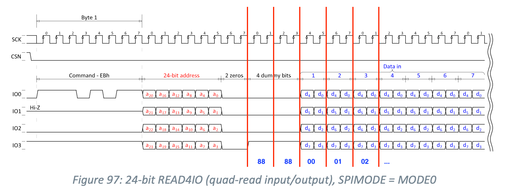
0x88 0x88 0x00 0x01 0x02 0x03 0x04 0x05 0x06 0x07 0x08 0x09 0x0a 0x0b 0x0c 0x0d
that is, the values of the first 2 bytes are wrong while the remaining bytes are correct but shifted.
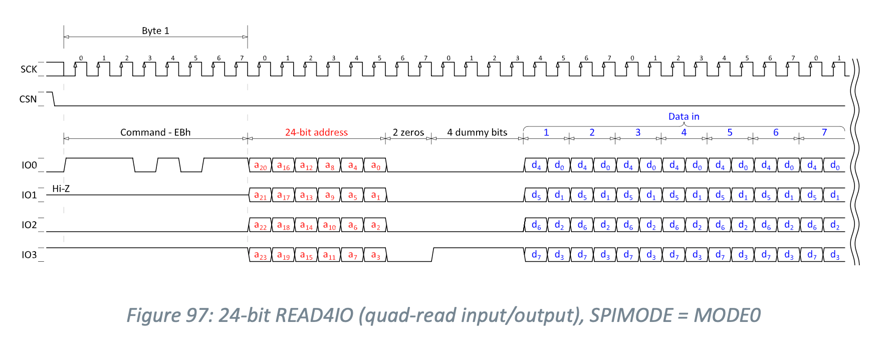
So I tried to understand where the problem is and, in the microcontroller datasheet, I found the signal diagram that it uses in case of reading with opcode 0xEB which I report below.

I don't know why but in my opinion the microcontroller starts reading from the 4 dummy cycles.
In fact the diagram shows the IO3 line high in the 4 dummy cycles and consequently the first 2 bytes are read with the values 0x88.

I contacted the memory manufacturer and this is what they replied:
- When you send the Quad I/O Read command (0xEB), the memory device expects a 3-byte address followed by the mode bits( Mode bits are optional control bits that follow the address bits).
- The mode bits are used to control the length of the next Quad I/O instruction and allow for address jumps.
- In your case, it seems that the microcontroller is not properly handling the mode bits, which is causing the device to start reading from the dummy cycles.
- During the dummy cycles, the IO3 line is high, which is why you're seeing the values 0x88 in the first two bytes of the read data.
- The remaining bytes are correct but shifted because the device is reading from the correct address, but the initial address is incorrect due to the misinterpreted mode bits
Can anyone help me figure out how to fix this problem?
Can the nRF52840 microcontroller handle mode bits? If so, how should I do it?
Thanks.
Stefano


