nrfjprog --readqspi unreliable

Hello,

I have a custom hardware, with an external 128MB QSPI flash memory connected to a nRF5340. My current task at hand, is to store firmware update images for MCUBoot there. The firmware is stored by the application using a custom driver for the external flash memory.

I've used nrfjprog already, to read measurement data from that external flash memory and that worked quite well. That's why it toke me quite some time to realize, that nrfjprog is doing something stupid here.

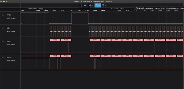
The external flash memory has a page size of 4kB and when reading the flash memory content, every first byte of every empty page reads 0x0f instead of 0xff. I changed the operations to be used to a single data line (read_mode = "FASTREAD"; write_mode = "PP") and slowed down the QSPI clock frequency to M2. Attaching a logic analyser, shows, that the flash memory response with 0xff (not 0x0f) to page read request.

Before opening this request, I updated the Segger JLink software to the newest version and then, the next try to read the flash content, showed the correct results! I did an other test and used `

west build --pristine -b"nrf5340dk/nrf5340/cpuapp" --build-dir ./build --sysbuild  .` && `west flash --recover ` to install new firmware on the nRF53. A following read, using nrfjprog showed again, wrong results (0x0f at the begin of every page), while the logic analyser still shows the correct picture.

I power reset, both custom hardware and debugger (J-Trace Pro) but that didn't fixed the issue. Combined with my observation from this ticket (https://devzone.nordicsemi.com/f/nordic-q-a/115570/using-mcuboot-with-nrf5340), that sometimes build errors are not reproducible, my suspicion is, that the `west build` or `west flash` command is changing some configuration data outside of the build folder.

I've used ´nrfjprog` a few month ago and could not find any issues. What changed to the project, was an update to nRF Connect SDK v2.7.99-cs2.

nrfjprog version: 10.24.2 external

JLinkARM.dll version: 8.10d

Here, a screen shot of the QSPI trace:

% nrfjprog --readqspi recording.bin --qspiini ./config.toml 
[ #################### ]   0.000s | Reading external memory, 0x200000 bytes @ 0x00000000 - Done                        
Storing data in 'recording.bin'.
% hexdump -C recording.bin | head                           
00000000  0f ff ff ff ff ff ff ff  ff ff ff ff ff ff ff ff  |................|
00000010  ff ff ff ff ff ff ff ff  ff ff ff ff ff ff ff ff  |................|

Attached is the entire trace and the used configuration file.

Best regards

Torsten

  • In the Safari version of this forum, every file upload erases the entire message, I will attache the other files in the next messages.

  • # nrfjprog configuration.
    [log]
        # level - A spdlog log level enumerator name. Case insensitive.
        # pattern - A spdlog log formatting pattern.
        # file - Target log file, will be written to in append mode. If file is a directory, or it's missing a file extension, "/log.log" will be appended to the log file path.
        [log.dll]
            # nrfjprogdll logger configuration
            level = "TRACE"
            pattern = "%v"
        [log.file]
            # nrfjprog executable file log sink configuration
            file = "log.log"
            level = "TRACE"
            pattern = "[%Y-%b-%d %H:%M:%S] [%5l] %v"
        [log.terminal]
            # nrfjprog executable terminal log sink configuration
            level = "ERROR"
            pattern = "[%5l] %v"
        
    [rtt]
        # If true, NRFJPROG_rtt_stop invalidates the current RTT control block. 
        # To restart RTT communication the target device must reinitialize the RTT control block before NRFJPROG_rtt_start is called.
        invalidate_control_block_on_stop = true
    
        # Set the period between rtt API calls in the async rtt worker threads. 
        # Shorter periods may improve performance, but can overwhelm the J-Link debug probe.
        async_read_period_ms = 10
        async_write_period_ms = 10
    
    [jlink]
        # If true, J-Link debug probe fw will be silently updated on NRFJPROG_connect_to_emu_with*().
        auto_update_fw=true
    
        # Controls for how long to attempt Debug Access Port (DAP) power down procedure before timing out.
        # nrfjprogdll will loop deassertion of the DAP CTRL/STAT CSYSPWRUPREQ and CDBGPWRUPREQ signals and check for acknowledgment.
        # See arm's description of the DAP CTRL/STAT register for more information.
        # Set to 0 to skip check for power down acknowledgment.
        dap_powerdown_timeout_ms = 1000
    
    [target]
        # Define the desired family of devices to use by default by nrfjprog.exe when -f or --family arguments are not used. 
        # Family identifiers are case insensitive, no suffixes, for example NRF51, nRF52, Nrf53 are all valid. 
        # If set to AUTO an automatic family detection will be performed. The autodetect family operation will take time, so it is advised to use correct family if known.
        family = 53
    
        # Define the desired clockspeed in kHz you want nrfjprog.exe use by default when -c or --clockspeed arguments are not used.
        clockspeed = 2000
    
        # ** Subject to change **
        # Write MPC override rules when enabling coprocessor (only when secure domain AHB-AP is available).
        # The rules will allow read/write of device memories, and is needed when SDFW is not present.
        # MPC rule writing is relevant for nRF54H family.
        # Valid options are:
        #   "AUTO"      Best effort write rules. Will not disable any active rules.
        #   "ALWAYS"    Always write if possible. Already enabled/active rules can be overwritten.
        #   "OFF"       Do not write rules.
        write_mpc_rules = "AUTO"
    
        # Write mode specifically for MPC000.
        # Overrides settings from "write_mpc_rules".
        write_mpc000_rules = "ALWAYS"
    
        # Write mode specifically for MPC110 override index 11
        # Overrides settings from "write_mpc_rules".
        write_mpc110_override11 = "ALWAYS"
    
        # How long to wait for a local domain to be started after a system reset.
        # On nRF54H, a local domain must be restarted by the Secure Domain firmware after a system reset.
        # Set to a negative value for no timeout.
        localdomain_started_timeout_ms = 7000
    
    
    [approtect]
        # Configurations for devices with hardened ap-protection.
    
        # Should nrfjprog write UICR APPROTECT registers after erasing?
        # Certain devices perform this write in hardware, in this case this configuration does nothing.
        write_uicr_approtect = true
        # Should nrfjprog verify UICR APPROTECT registers?
        # On certain devices UICR->APPROTECT is written automatically to some reset value != 0xFFFFFFFFF
        # on erase. On these devices it's not possible to directly compare this NVM register to image file contents.
        verify_uicr_approtect = false
        # Should nrfjprog cli write an unlock image to NVM memory after --recover?
        # Certain devices require this image to stay unlocked.
        install_unlock_image = true
    
    # nrfjprog QSPI configuration.
    [qspi]
        # Define the capacity of the non-volatile memory device in bytes. Set to 0 if no external memory device is present in your board.
        #mem_size = 0x800000
        mem_size = 0x200000
    
        # Define the desired ReadMode. Valid options are FASTREAD, READ2O, READ2IO, READ4O and READ4IO
        read_mode = "FASTREAD"
        #read_mode = "READ4O"
    
        # Define the desired WriteMode. Valid options are PP, PP2O, PP4O and PP4IO
        write_mode = "PP"
        #write_mode = "PP4IO"
    
        # Define the desired AddressMode. Valid options are BIT24 and BIT32
        address_mode = "BIT32"
    
        # Define the desired Frequency. Valid options are M2, M4, M8, M16 and M32
        frequency = "M2"
        #frequency = "M16"
    
        # Define the desired SPI mode. Valid options are MODE0 and MODE3
        spi_mode = "MODE0"
    
    
        # Define SPI interface timing. Valid options are in the range of 0 to 7.
        # This argument is only used for devices where the dll function NRFJPROG_qspi_set_rx_delay() is supported.
        rx_delay = 2
    
        # Define the Index of the Write In Progress (WIP) bit in the status register. Valid options are in the range of 0 to 7.
        wip_index = 0
    
        # Define page size for commands. Valid sizes are PAGE256 and PAGE512.
        page_program_size = "PAGE256"
        
        # If retention is enabled, device RAM contents will be read and buffered during QSPI driver initialization.
        # The buffered data will be written back to the device when unitializing the driver, restoring the original device RAM state.
        # Enabled: retain_ram = true, Disabled: retain_ram = false
        retain_ram = false
    
        # Define the assigned pins for the QSPI peripheral. Valid options are those existing in your device
        # For nRF53, QSPI pins are not configurable and these values are ignored.    
        [qspi.sck]
            # Define the desired SckDelay. Valid options are in the range 0 to 255
            delay = 0x80
            pin = 19
            port = 0
    
        [qspi.csn]
            pin = 17
            port = 0
        [qspi.dio0]
            pin = 20
            port = 0
        [qspi.dio1]
            pin = 21
            port = 0
        [qspi.dio2]
            pin = 22
            port = 0
        [qspi.dio3]
            pin = 23
            port = 0
    
        [qspi.custom]
            # Define the desired IO level for DIO2 and DIO3 during a custom instruction. Valid options are LEVEL_HIGH and LEVEL_LOW
            io2_level = "LEVEL_LOW"
            io3_level = "LEVEL_HIGH"
    
            # Custom instructions to send to the external memory after initialization. Format is instruction code plus data to send in between optional brakets. 
            # These instructions will be executed each time the qspi peripheral is initiated by nrfjprog. 
            # To improve execution speed on consecutive interations with QSPI, you can run nrfjprog once with custom initialization, and then comment out the lines below.
            # Numbers can be given in decimal, hex (starting with either 0x or 0X) and binary (starting with either 0b or 0B) formats. 
            # The custom instructions will be executed in the order found. 
            # This example includes two commands, first a WREN (WRite ENable) and then a WRSR (WRite Satus Register) enabling the Quad Operation and the High Performance
            # mode for the MX25R6435F memory present in the nRF52840 DK.
            instructions =  [
                {command=0x06, data=[]},
                {command=0x01, data=[0x40, 0, 0x2]},
                {command=0x06, data=[]},
                {command=0xB7, data=[]}
            ]
    
    [system]
        # If true, the underlying jlinkarm_nrf_worker process will ignore SIGINT, SIGTERM, SIGABRT, SIGILL and SIGSEGV signals.
        # It is strongly recommended to keep this as false for nrfjprog exe.
        # This feature is mainly inteded for use with the pynrfjprog API, where you sometimes want to manually handle a ctrl-c event without the signal
        # propagating to the jlinkarm_nrf_worker process.
        worker_ignore_signals = false
    
    nrfjprog.sal

  • One addition data point: When I used my original QSPI configuration (read_mode = "READ4O", write_mode = "PP4IO" and frequency = "M16"), the effect was, that the first two bytes of every empty pages reads as 0x88, 0x88. I will also attach a log file from `nrfjprog`.

  • Hello,

    According to the nRF5340's QSPI documentation, only the dedicated QSPI pins should be used for QSPI:

    https://docs.nordicsemi.com/bundle/ps_nrf5340/page/qspi.html#ariaid-title2

    So it could be that what you are seeing is a result of this. 

    Is it too late to change the GPIOs?

    Best regards,

    Edvin

Related