Differences between IQ Data

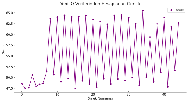
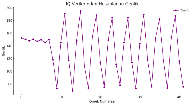
Hello everyone, I have two nrf5340 kits. I run "Bluetooth Direction Connectionless" applications with these kits. I also have a CoreHW brand AoA antenna. My question to you is, the code is completely native, I plotted the IQ data I received at two different times as amplitude, but there is a clear difference in the sampling timings between them. What is the reason for this? Please pay attention to the positions marked with dots. My question is, is it possible to give an offset in the sampling time? If the answer is yes, can you help me with this? (I plotted my languange so bottom of the graphic means to sample number and left side of the graphic means to amplitude)

Parents
  • Hi

    Are both of your kits nRF5340 DKs or are these two slightly different boards? I assume you're using the CoreHW AOA antenna as a receiver/locator, correct? Do you have the same exact application running on the two devices or are you using different configs, board files or overlays that might be adding some issues here? The second graph seems to be offset somehow indeed, and that could be due to a mismatch of PHY, sampling slots or similar I think. But I need some more information on what exactly is being measured here. Is this just raw IQ data or have you run it through an AOA algorithm on the receiver side?

    Best regards,

    Simon

Reply
  • Hi

    Are both of your kits nRF5340 DKs or are these two slightly different boards? I assume you're using the CoreHW AOA antenna as a receiver/locator, correct? Do you have the same exact application running on the two devices or are you using different configs, board files or overlays that might be adding some issues here? The second graph seems to be offset somehow indeed, and that could be due to a mismatch of PHY, sampling slots or similar I think. But I need some more information on what exactly is being measured here. Is this just raw IQ data or have you run it through an AOA algorithm on the receiver side?

    Best regards,

    Simon

Children
  • Hello, yes, I use it on both the receiver and transmitter side. Also, as you said, I am constantly changing the signal PHYs and slot times and trying to take samples. I am not using any tools other than the system provided by Nordic. After taking various samples, I am trying to visualize all IQ data with Python for analysis. However, during these attempts, I encountered the situation I mentioned. Frankly, I am curious about the reason for this. Also, apart from sampling spacing and switching spacing, I am questioning whether an offset structure for sampling can be made on the Nordic side. For example, sample space 2us, switch space 2us and sample offset 1 us. According to my guesses, instead of taking data from the moment it is switched, it is necessary to take samples with a certain offset in the existing sampling interval.

    Best Regards.

Related