Flash MEM through SPI not response

Hi, in our project we use the nRF52832 and a external flash memory MX25L3206E connected on this pins:
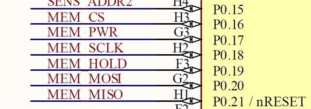
Take note in this project we also use SPIM0 to manage an IMU and SPIM2 to flash with this configuration:

//! GPIO FLASH power port number
#define HARDWARE_INIT_FLASH_PORT_NUMBER                                     0
//! GPIO FLASH power pin number
#define HARDWARE_INIT_FLASH_POWER_PIN_NUMBER                                17
//! GPIO FLASH write protect (WP) pin number
#define HARDWARE_INIT_FLASH_WP_PIN_NUMBER                                   5
//! GPIO FLASH hold pin number
#define HARDWARE_INIT_FLASH_HOLD_PIN_NUMBER                                 19

//! SPI FLASH MEMORY port number 
#define HARDWARE_INIT_FLASH_SPI_PORT_NUMBER                                 0
//! SPI FLASH MEMORY CS pin number 
#define HARDWARE_INIT_FLASH_SPI_CS_PIN_NUMBER                               16
//! SPI FLASH MEMORY SCLK pin number 
#define HARDWARE_INIT_FLASH_SPI_SCLK_PIN_NUMBER                             18
//! SPI FLASH MEMORY MOSI pin number 
#define HARDWARE_INIT_FLASH_SPI_MOSI_PIN_NUMBER                             20
//! SPI FLASH MEMORY MISO pin number 
#define HARDWARE_INIT_FLASH_SPI_MISO_PIN_NUMBER                             21

//! SPI KX122 ACCELEROMETER SPI port number
#define HARDWARE_INIT_KX122_SPI_PORT_NUMBER                                 0
//! SPI KX122 ACCELEROMETER CS pin number
#define HARDWARE_INIT_KX122_SPI_CS_PIN_NUMBER                               4
//! SPI KX122 ACCELEROMETER MISO pin number
#define HARDWARE_INIT_KX122_SPI_MISO_PIN_NUMBER                             26
//! SPI KX122 ACCELEROMETER MOSI pin number
#define HARDWARE_INIT_KX122_SPI_MOSI_PIN_NUMBER                             25
//! SPI KX122 ACCELEROMETER SCLK pin number
#define HARDWARE_INIT_KX122_SPI_SCLK_PIN_NUMBER                             11
//! INT1 KX122 ACCELEROMETER interruption 1 pin number
#define HARDWARE_INIT_ACC_INT1_PIN_NUMBER                                   30
//! INT2 KX122 ACCELEROMETER interruption 2 pin number
#define HARDWARE_INIT_ACC_INT2_PIN_NUMBER                                   31 

	{
		.misoPinIdentifier = HARDWARE_INIT_KX122_SPI_MISO_PIN_NUMBER,
		.misoPortConfig = HARDWARE_INIT_KX122_SPI_PORT_NUMBER,
		.mosiPinIdentifier = HARDWARE_INIT_KX122_SPI_MOSI_PIN_NUMBER,
		.mosiPortConfig = HARDWARE_INIT_KX122_SPI_PORT_NUMBER,
		.sclkPinIdentifier = HARDWARE_INIT_KX122_SPI_SCLK_PIN_NUMBER,
		.sclkPortConfig = HARDWARE_INIT_KX122_SPI_PORT_NUMBER,
		.ccsPinIdentifier = HARDWARE_INIT_KX122_SPI_CS_PIN_NUMBER, 
		.ccsPortConfig = HARDWARE_INIT_KX122_SPI_PORT_NUMBER, 
		.spiFrequency = HAL_SPI_FREQUENCY_1M,
		.spiClockPolarity = HAL_SPI_CPOL_LOW, 
		.spiClockPhase = HAL_SPI_CPHA_LOTOHI,
		.spiMasterInstance = NRFX_SPIM_INSTANCE(0)
	},
	{
		.misoPinIdentifier = HARDWARE_INIT_FLASH_SPI_MISO_PIN_NUMBER,
		.misoPortConfig = HARDWARE_INIT_FLASH_SPI_PORT_NUMBER,
		.mosiPinIdentifier = HARDWARE_INIT_FLASH_SPI_MOSI_PIN_NUMBER,
		.mosiPortConfig = HARDWARE_INIT_FLASH_SPI_PORT_NUMBER,
		.sclkPinIdentifier = HARDWARE_INIT_FLASH_SPI_SCLK_PIN_NUMBER,
		.sclkPortConfig = HARDWARE_INIT_FLASH_SPI_PORT_NUMBER,
		.ccsPinIdentifier = HARDWARE_INIT_FLASH_SPI_CS_PIN_NUMBER, 
		.ccsPortConfig = HARDWARE_INIT_FLASH_SPI_PORT_NUMBER, 
		.spiFrequency = HAL_SPI_FREQUENCY_1M,
		.spiClockPolarity = HAL_SPI_CPOL_LOW, 
		.spiClockPhase = HAL_SPI_CPHA_LOTOHI,
		.spiMasterInstance = NRFX_SPIM_INSTANCE(2)
	}

This is the prj.conf of the project:

# Drivers selection

CONFIG_GPIO=y
CONFIG_GPIO_AS_PINRESET=n
CONFIG_SERIAL=y
# UARTE
#CONFIG_NRFX_UARTE1=n
#CONFIG_NRFX_UARTE0=y
CONFIG_LOG=n
CONFIG_LOG_DEFAULT_LEVEL=3
CONFIG_WATCHDOG=y

CONFIG_ADC=y
CONFIG_ADC_ASYNC=y
CONFIG_ADC_NRFX_SAADC=y

CONFIG_PINCTRL=y
CONFIG_I2C=y
#CONFIG_NRFX_TWIM1=y
CONFIG_FLASH=y
CONFIG_SPI=y
CONFIG_SOC_NRF52832_ALLOW_SPIM_DESPITE_PAN_58=y
CONFIG_NRFX_SPIM0=y
CONFIG_NRFX_SPIM2=y

CONFIG_FLASH_PAGE_LAYOUT=y
CONFIG_MPU_ALLOW_FLASH_WRITE=y
CONFIG_SOC_FLASH_NRF_EMULATE_ONE_BYTE_WRITE_ACCESS=y

CONFIG_REBOOT=y #n

# Power management
# CONFIG_PM=y
# CONFIG_PM_DEVICE=y
# CONFIG_POWEROFF=y
 
# Interrupts
# CONFIG_DYNAMIC_INTERRUPTS=n
# CONFIG_UART_INTERRUPT_DRIVEN=n
# CONFIG_IRQ_OFFLOAD=n

# Stacks and heaps   
# This configuration reserve 20K of RAM to HEAP, this project only has 64K 
# and all the code is the 98% of the RAM so we can not declare so much heap
CONFIG_HEAP_MEM_POOL_SIZE= 8000
#CONFIG_HEAP_MEM_POOL_SIZE= 6144
CONFIG_MAIN_STACK_SIZE=1024
CONFIG_SYSTEM_WORKQUEUE_STACK_SIZE=4096
#CONFIG_NET_TX_STACK_SIZE=512
#ONFIG_NET_RX_STACK_SIZE=512
# CONFIG_NET_MGMT_EVENT_STACK_SIZE=2048

# Memory protection
# CONFIG_THREAD_STACK_INFO=n
# CONFIG_THREAD_CUSTOM_DATA=n
# CONFIG_FPU=n

# BLE configuration
CONFIG_BT=y
CONFIG_SETTINGS=y
CONFIG_BT_PERIPHERAL=y
CONFIG_BT_GATT_DYNAMIC_DB=y

#CONFIG_BT_PERIPHERAL_PREF_MIN_INT=6
#CONFIG_BT_PERIPHERAL_PREF_MAX_INT=9
#CONFIG_BT_PERIPHERAL_PREF_LATENCY=99
#CONFIG_BT_PERIPHERAL_PREF_TIMEOUT=400
#CONFIG_BT_GAP_AUTO_UPDATE_CONN_PARAMS=y

CONFIG_BT_DEVICE_NAME="Tarsos Device"

CONFIG_BT_L2CAP_TX_MTU=252
CONFIG_BT_BUF_ACL_TX_SIZE=251
CONFIG_BT_BUF_ACL_RX_SIZE=502

#CONFIG_BT_SMP=y
#CONFIG_BT_SIGNING=y
#CONFIG_BT_PERIPHERAL=y
#CONFIG_BT_DIS=y
#CONFIG_BT_ATT_PREPARE_COUNT=5
#CONFIG_BT_BAS=y
#CONFIG_BT_HRS=y
#CONFIG_BT_IAS=y
#CONFIG_BT_PRIVACY=y
#CONFIG_BT_DEVICE_APPEARANCE=833
#CONFIG_BT_DEVICE_NAME_DYNAMIC=y
#CONFIG_BT_DEVICE_NAME_MAX=65

#CONFIG_BT_KEYS_OVERWRITE_OLDEST=y
#CONFIG_BT_SETTINGS=y

# Debug configuration
CONFIG_DEBUG=y
CONFIG_DEBUG_OPTIMIZATIONS=y
CONFIG_DEBUG_THREAD_INFO=y

The problem is that the IMU works fine due to it rsponse his ID number and other data, but when we try to comunicate with the flash memory to see the iID number it return in our buferRX all ones,
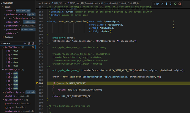
Could you any chech this and explain why SPIM0 works fine and SPIM2 no?

Many thanks in advance.

Parents
  • Hi,

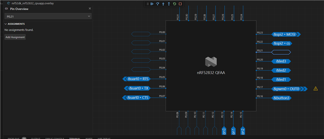
    I suspect that pin 0.21 is still configured as a reset pin. The default behaviour of the SoC is for the pin to be used as a GPIO, but several tools will default to configuring it as a reset pin in the UICR.

    First of all, make sure you define it as a GPIO (or not a reset pin) in the devicetree. The Kconfig option CONFIG_GPIO_AS_PINRESET which had the same purpose is no longer used. This this post for more details on that.

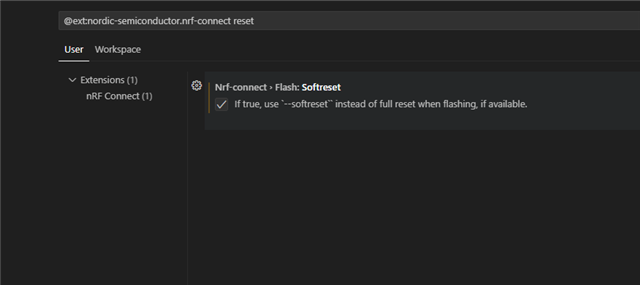
    Secondly, when you program with west from the command line or nRF Connect from VS Code, the default behaviour is also to enable pin reset at that stage. To avoid that, make sure to append "--softreset" if programming directly from west. And if programming from VS Code, make sure to edit the settings and enable. SoftReset. I prefer to search for the settings and then find the check-box that way:

  • Hi Einar, thanks for your support.

    This is the devitree:

    The P0.21 hasn't any assignament.

    This is the Kconfig file and doesn't has the CONFIG_GPIO_AS_PINRESET.

    source "Kconfig.zephyr"
    
    menu "Proxximos Anchor Kconfig"
    
    config CONNECTION_IDLE_TIMEOUT
    	int "Time to be waited for a station to connect"
    	default 30
    
    config SSID
    	string "SSID"
    	help
    		Specify the SSID to connect
    
    choice KEY_MGMT_SELECT
    	prompt "Security Option"
    	default KEY_MGMT_WPA2
    
    config KEY_MGMT_NONE
    	bool "Open Security"
    	help
    	  Enable for Open Security
    
    config KEY_MGMT_WPA2
    	bool "WPA2 Security"
    	help
    	  Enable for WPA2 Security
    endchoice
    
    config PASSWORD
    	string "Passphrase (WPA2) or password (WPA3)"
    	help
    	  Specify the Password to connect
    
    config BUILD_DFU
    	bool "Include DFU Configuration on the project"
    	default n
    
    if ARM_MPU
    config MPU_ALLOW_FLASH_WRITE
    	def_bool y
    endif
    
    endmenu

    Normaly I use VS Code for programming and the Softreset is enabled on settings.

Reply
  • Hi Einar, thanks for your support.

    This is the devitree:

    The P0.21 hasn't any assignament.

    This is the Kconfig file and doesn't has the CONFIG_GPIO_AS_PINRESET.

    source "Kconfig.zephyr"
    
    menu "Proxximos Anchor Kconfig"
    
    config CONNECTION_IDLE_TIMEOUT
    	int "Time to be waited for a station to connect"
    	default 30
    
    config SSID
    	string "SSID"
    	help
    		Specify the SSID to connect
    
    choice KEY_MGMT_SELECT
    	prompt "Security Option"
    	default KEY_MGMT_WPA2
    
    config KEY_MGMT_NONE
    	bool "Open Security"
    	help
    	  Enable for Open Security
    
    config KEY_MGMT_WPA2
    	bool "WPA2 Security"
    	help
    	  Enable for WPA2 Security
    endchoice
    
    config PASSWORD
    	string "Passphrase (WPA2) or password (WPA3)"
    	help
    	  Specify the Password to connect
    
    config BUILD_DFU
    	bool "Include DFU Configuration on the project"
    	default n
    
    if ARM_MPU
    config MPU_ALLOW_FLASH_WRITE
    	def_bool y
    endif
    
    endmenu

    Normaly I use VS Code for programming and the Softreset is enabled on settings.

Children
  • Hi,

    The DK devicetree files will by default configure the pin as a reset pin. As you are using the the DK files with an overlay, you need to also then delete the gpio-as-nreset property as shown in this post.

  • Hi,

    This is the overlay text file:

    // To get started, press Ctrl+Space to bring up the completion menu and view the available nodes.
    
    // You can also use the buttons in the sidebar to perform actions on nodes.
    // Actions currently available include:
    
    // * Enabling / disabling the node
    // * Adding the bus to a bus
    // * Removing the node
    // * Connecting ADC channels
    
    // For more help, browse the DeviceTree documentation at https://docs.zephyrproject.org/latest/guides/dts/index.html
    // You can also visit the nRF DeviceTree extension documentation at https://nrfconnect.github.io/vscode-nrf-connect/devicetree/nrfdevicetree.html
    
    &spi0 {
        status = "okay";
        compatible = "nordic,nrf-spim";
    };
    
    &spi1 {
        status = "disabled";
    };
    
    &spi2 {
    	status = "okay";
        compatible = "nordic,nrf-spim";
    };
    
    &i2c1 {
        status = "okay";
        compatible = "nordic,nrf-twim";
    };
    
    &i2c0 {
        status = "disabled";
    };
    
    &flash0 {
    	partitions {
    		#address-cells = <1>;
    		#size-cells = <1>;
    		compatible = "fixed-partitions";
    
    		
    		/* Set 3Kb of storage at the end of the of 2Mb flash 0 */
    		/*
    		storage_partition: partition@f8000 {
    			label = "storage";
    			reg = <0xf8000 DT_SIZE_K(3)>;
    		};
    		*/
    	};
    };
    
    &power {
        status = "disabled";
    };
    
    &uart0_sleep {
        group1 {
            psels = <NRF_PSEL(UART_TX, 0, 6)>, <NRF_PSEL(UART_CTS, 0, 7)>;
        };
    };
    
    &uart0_default {
        group1 {
            psels = <NRF_PSEL(UART_TX, 0, 6)>, <NRF_PSEL(UART_CTS, 0, 7)>;
        };
    };
    
    &uicr {
        /delete-property/ gpio-as-nreset;
        status = "okay";
    };
    

    And still not works.

  • Hi,

    I see. With that using the P0.21 should be OK as long as you have done a recover/erase all to clear the UICR (you can always read back the PSELRESET registers from a debugger to verify that it is the case). However, the overlay file does not properly describe the spim instance used for the external memory? You would want something similar to what is shown in this file.

  • Hi Mr. Einar.

    I tried the same code on test board nRF52 DK adding the parameter on the .overlay file (/delete-property/ gpio-as-nreset;) but when I cross the MISO pin P0.20 and MOSI pin P0.21 to read the data I send the uC fall down because the pin P0.21 still configurated as reset.

    About the &spim description in overlay file for the &spi0 also has the same parameters but this works fine.

    Could you provide another soultion or explain better how configure the parameters for &spim2?

    Regards.

  • Hi,

    Did you perform an erase all operation (for instance nrfjprog --recover) when you programmed the new firmware? That is requiered in order to erase the UICR and make the pin a GPIO again, as that configuration is persistent if you do not and earlier firmware enabled pin reset. If it still does not work, can you share the generated .config and zephyr.dts from your build folder so that we see which configuration is actually being used? Also, which SDK version are you using?

Related