A short circuit between the SIM_1V8 pin and GND in nRF9160

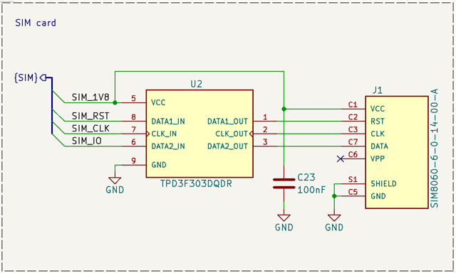
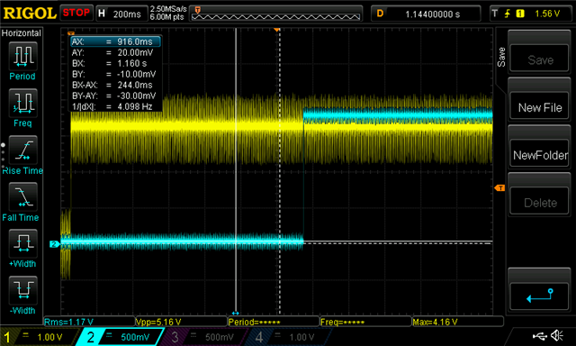
I ordered my second prototype board with the nRF9160, which includes small changes compared to the previous version. I encountered an issue with LTE connectivity. After some checks and hardware verification, I noticed that the SIM card is not being supplied with power. During system startup and while attempting to connect to the network, a few microvolts appear briefly on the SIM_1V8 pin for a few milliseconds. It seems like the microcontroller is trying to power the SIM card.

After further investigation, I found that the nRF9160 chip has a short circuit between the SIM_1V8 pin and GND. I desoldered the microcontroller and confirmed that the short circuit is within the nRF9160 chip itself; the PCB is unaffected. In comparison, the short circuit does not occur in the previous prototype version, which worked well and connected to the network without issue.

I received two assembled prototypes, and both exhibit the same problem. However, the previous prototypes worked correctly, and the chip was able to connect to the network properly.

I’m wondering if there’s an option in the microcontroller that needs to be enabled to supply 1.8V to the SIM card?

The difference between the chips used in the prototypes is as follows:

  • Current prototypes: nRF9160 SICA B1 2230JF (with short circuit)
  • Previous prototypes: nRF9160 SICA B1 2231JU (working properly)

I am using:

  • SDK v2.5.1
  • nRF Toolchains v2.5.1
  • Modem MFW v1.3.6
  • This is the schematic corresponding to the SIM. The SIM bus is connected directly to the SiP. The U2 is the EMI filter for the SIM interface.

    This is the first working prototype. The yellow line is the SiP power supply (3.3V), the blue line is the 1V8_SIM. The 1.8V is always present.

  • Hi Bartlomiej,
    I assume the resistance along the line from SIM_1V8 to VCC on U2 and VCC on J1 are all ok with the SiP removed? Ok as in you see infinite resistance/open circuit once the SiP is desoldered from the failing prototype? What sort of resistance do you measure along SIM_1V8 and VCC on U2/J1 on the failing prototype that still has the SiP soldered on?
    The most likely cause is unfortunately something has shorted two or more pads on the SiP during the manufacturing process. How long were they running before you started probing the SIM_1V8 lines?
    Best regards
    Asbjørn
  • Hi Asbjørn,

    Sorry for replying on an older chat. Only I have the same issue.

    We had 2 production runs:

    1. First prototype run of 4 fully assembled PCB's by a good production company. From these 4 PCB's had 2 issues with the SIM_1V8.

    2. Second run of 16 assembled PCB's by the same production company (they also installed these PCB's in the final enclosure). From these 16, one had an problem with hte SIM_1V8.

    Both issues, 3 PCB's in total, had the exact same behavior as is described by Bartlomiej.

    • When NRF9160 is soldered on the PCB, there is a short (less then 3 ohm) on the PCB on the SIM_1V8 trace.
    • When I remove the NRF9160, there is no short on the PCB SIM_1V8 trace.
    • If I measre the NRF9160 between the SIM_1V8 pad and any GND_Shield pad.

    Yes there were changes on the PCB, only those were not related to the NRF9160 or the eSIM to which the SIM_1V8 is connected. The production company we use, also regulary verify if there reflow process is correct. 

    If they manage to produce 17 out of 20 correct PCB's I deduce there is not something inherently wrong with the production process. There most be something else that makes the SIM_1V8 very sensitive. I assume you would have had more quality issues from other customers. is this correct?

  • Hello RemcovH,
    I  initially though you were following up from the same company and batch that Bartlomiej is, but I see now that you are working on different product, but see similar behaviour from small production run.
    Firstly, since this is a different board and setup, I think it would be better to create a separate DevZone ticket to track your question on and then we reference this case. It does seem like you are seeing similar outcome. When it comes to your question about quality, we do from time to time see customers that are doing small batches come back with similar questions, but not from larger scale builds. 
    We suspect it's related to the solder paste used, the solder stencils and generally the assembly heat transfer through the board that creates this. On smaller batches it's often more prone to human judgements on times and temperatures, so you'll see some differences. We don't think there's just one issues with these, but the package is challenging on small scale productions runs.
    So if I may, please create a separate ticket on this for your scenario and we'll work through the behaviour. Link to this case so others can see if you'd like to. 
    Best regards
    Asbjørn
  • Hello Everyone,

    We are experiencing the same issue with the silicon SICA B1 2230JF. Some boards from two different batches are exhibiting the described problem. The IC shows a short between the SIM_1V8 pin and GND, even after it has been unsoldered.

    We have not identified any design flaws, and everything appears normal on the X-ray inspection. Other batches of ICs do not seem to have this issue.

    Do you have any recommendations on how we can eliminate this problem?

Related