Errata 219 is incomplete or misleading. Unexpected behaviour at 100kHz. TWIM clock too short after clock stretch.

Potential TLDR:

The nRF52 and possibly nRF53 are unusable at 100kHz with targets that require clock stretching and enforce a reasonable minimum clock period. This covers a very broad selection of targets, in particular lot of TI parts included in COTS battery packs.

Context:

nRF52840 on PC10056 dev board operating as an I2C controller with a target that uses clock stretching while operating at "standard speed" (100kHz).

nRF Connect SDK v2.7.0-5cb85570ca43

Dev kit has DETECT (shield detect) pulled low to enable the onboard pull ups.

I note that there are quite a few semi-related previous posts, however the threads contain a lot of conjecture and hand waving. None that I have found really get to the bottom of the issue or have a viable solution. 

This issue has come up on pre-production hardware as an intermittent bug, I have replicated it on the dev kit to avoid distraction about hardware. However this is problem in a mature project with considerable NRE behind it.
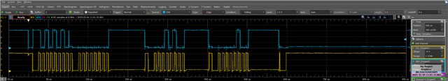
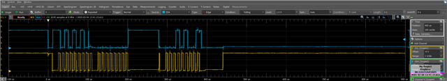
Issue observed

When reading from the target (and possibly in other transactions) with i2c_write_read_dt() the TWIM occasionally produces a significantly shortened clock pulse after the target stretches the clock. I have observed this in particular on first clock after a stretch, after the controller has sent an ack in response to a byte from the target. I suspect I have seen it elsewhere, however, that was before I appreciated what I was looking at. 

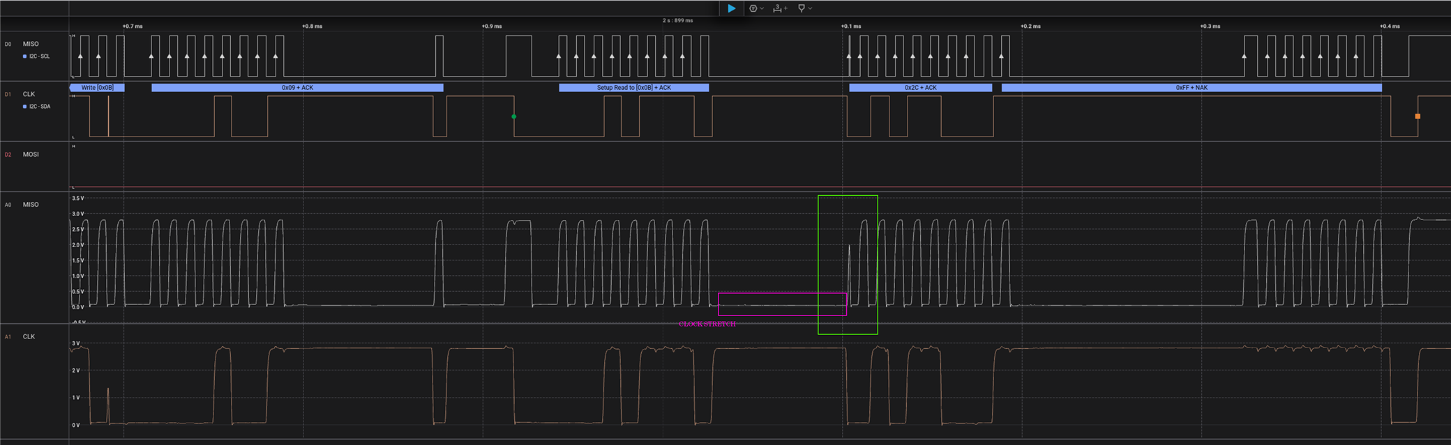
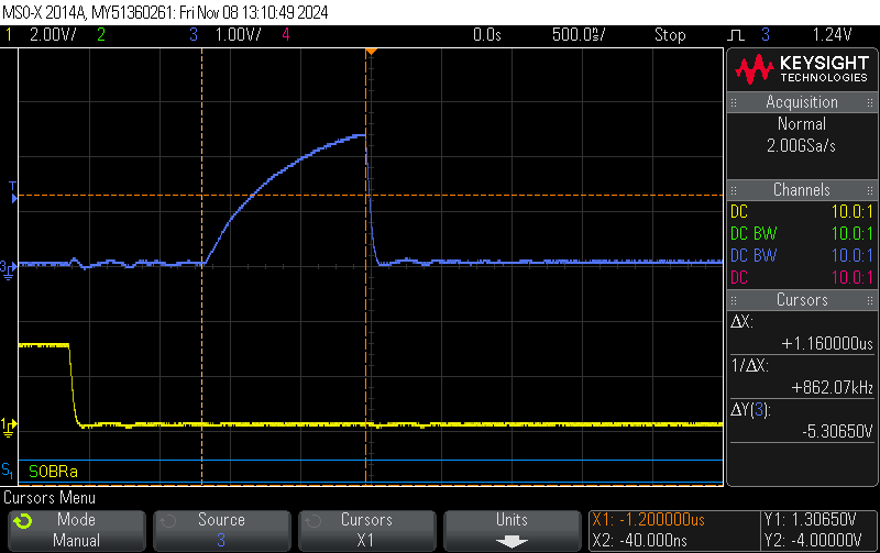
The shortened clock is of varying length down to 1.2us, when optimistically measured at the first observable change in the trace. In practice, after considering thresholds for high and low, it ends up in the region of 850ns from the point of view of the target in a practical design.

In this case, the target disregards clock periods under 4us. A feature that mitigates the effect of noise on SCL. Not an unreasonable margin of 20% from the expected 5us clock period. 

If there is any doubt about this being a feature, I have seen the lack of this feature in other targets cause no end of headache during compliance testing. An example result being a locked up bus during ESD testing. 

It is also of note that even if the bus had no capacitance and the pull ups were magic resulting in no rise time, the clock pulse is still only 1.2us. 

Errata:

The only mention of TWIM in the errata document(r3) is errata 219, TWIM: I2C timing spec is violated at 400 kHz. This errata states:

Conditions: Using TWIM at 400 kHz.

It seems very reasonable to consider this errata as not applicable when operating at 100kHz. In fact, on first reading, it appears that 100kHz would be a viable mitigation for problems at 400kHz.

If short clocks are considered an error at 400kHz, resulting in an errata. Surely this would also be considered an error at 100kHz where expectations on valid clock length would be longer. Noting that if the device does not conform to a documented standard (eg I2C) and does not provide full documentation on behaviour, a user can only work from reasonable expectation. The datasheet does not seem to document the minimum clock high period to highlight that it is not as might be expected.

Mitigation:

Working on the principle that this is the issue documented in errata 219 is highly likely to be the same thing, I tested the workaround provided with the FREQUENCY value scaled to match the context of 100kHz. This does not resolve the issue. Even with the clock speed reduced to ~12kHz the TWIM is producing clock pulses at ~1.2uS.

I have looked at using the bit-bang driver in zephyr, it did not work fully, requiring more debugging. Also, the bus is used quite a bit elsewhere in the system so bit-banging is not really an acceptable route to go.

Other parts:

Given that we are strongly tied into the nordic ecosystem with a lot of sunk NRE, we could consider moving to a different part. I note that the nRF5340 errata Rev1 v1.9 contains the same errata, almost word for word as ID47. Presuming that this means it has inherited the same peripheral IP block, including the issue. It seems that moving to the nRF53 will not solve the issue. The nRF54  does not currently have any public documentation.

Conclusion:

The nRF52 and possibly nRF53 is unusable at 100kHz with targets that require clock stretching and enforce a reasonable minimum clock period. This covers a very broad selection of targets, in particular lot of TI parts included in COTS battery packs.

Questions:

1) Is there a mitigation for this other than bit banging or is it simply impossible to use nordic BLE parts for many "I2C" applications? 

2) Should the errata not be more clear that it applies (even more so) at standard speed (100kHz). 

3) Does this also apply to the nrF53?

4) Has the issue been carried to the nRF54 or is this a potential route out of a corner?

Thanks in advance.

Tom

EDIT: Corrected errata no

  • So I am having this issue where after a NACK (its clock pulse seems awfully short) and the SDA line does not lift. I want to make sure this is the same issue before proceeding to test these workarounds.

  • Looks to me like there are 3 clock stretches here, 1st 90uSec ok, 2nd 60uSec ok, 3rd 80uSec has short clock pulse. Using just the timer to hold off transmission for 100uSec would mean the short clock pulse would not occur, it would stay high for the duration of SUSPEND, so SUSPEND on every clock edge (some of these SUSPENDs are of course redundant but I think benign) and also clear and start the Timer on each clock pulse, then the timer issues the RESUME and timer stop after 100uSec (or maybe 200 uSec).

    What can go wrong? Well the assumption is that SUSPEND really does suspend so the SCL doesn't get pushed low after that short rising edge, and that's a question for Nordic hardware guys.

    16MHz clock with SCL at 100kHz is 160 16M clocks per clock; I suspect there is a race hazard internally that shows up if the external asynchronous event - the end of the hold-SCL-low clock stretch - is not an integer multiple (or close to) of 160 16M clocks. Funnily enough the one that fails is the one that is an integer multiple.

    Will this work? Best I can think of without hardware design changes ..

    Edit: Maybe you could look at the numbers more accurately than I can for the discussion on the race hazard, no help for us but would allow Nordic to fix the issue in the next die revision :-)

    Edit2: Worst case if this doesn't work try having a spare open-drain output pin H0D1 to be driven low every 8 clock edges to force a clean known-width (using 100uSec timer) stretch after every byte.

  • So I took some more measurements and found that there extra pulse is present:

    Will try out the workarounds and see if it improves the reliability of the communication.

  • Uh-oh, that last trace shows more clearly that the TI slave is clock-stretching before the ACK/NAK clock pulse, presumably so that it can decide whether to Ack or Nak the data byte. SUSPEND activates after the ACK/NAK clock cycle, so that solution won't work - pity.

    Proposal:

    • Set a spare port pin to be H0D1 output
    • Start a Timer at the same time as the TWIM events STARTED using PPI
    • Set the Timer CC[0] register to trigger the spare port pin Low via PPI after a time equal to 9 x SCL clock cycles, say 90 uSecs, after the 9th clock and coincident with a slave clock stretch if one is in progress but before the next byte clock if no slave stretch is in progress
    • Set the Timer CC[1] to clear the timer and set the port pin High (actually float as open-drain) via PPI to end the synchronous stretch say after another 100uSec, ie at 190uSec
    • Stop and Clear the Timer and set the port pin High (actually float as open-drain) on the TWIM events STOPPED using PPI
    • Tune this synchronous stretch to be longer than the longest slave stretch but without generating the race-hazard pulse

    I think this should work; the spare output pin should be connected to the SCL to extend the stretch initiated by the TI slave by a (safe) synchronous amount, or if no added stretch from the slave it will add a spurious (but safe) stretch. The clocks for both TWIM and Timer are synchronous from 16MHz regardless of whether using the crystal. The synchronous stretch is added for every byte regardless of whether requested by the slave, but who cares.

    Edits in progress; I may even test this ..

  • Looks like the steps I outlined work by using a single timer and an output pin which provides a synchronous stretch. Not sure about the CC numbers, would have to test with the application.

    // Errata 219 - Proof of concept work-around
    //
    // Set a spare port pin to be H0D1 output
    // Start a Timer at the same time as the TWIM events STARTED using PPI
    // Set the Timer CC[0] register to trigger the spare port pin Low via PPI after a time equal to 9 x SCL
    //  clock cycles, say 90 uSecs, after the 9th clock and coincident with a slave clock stretch if one is
    //  in progress but before the next byte clock if no slave stretch is in progress
    // Set the Timer CC[1] to clear the timer and set the port pin High (actually float as open-drain) via
    //  PPI to end the synchronous stretch say after another 100uSec, ie at 190uSec
    // Stop and Clear the Timer and set the port pin High (actually float as open-drain) on the TWIM events
    //  STOPPED using PPI
    // Tune this synchronous stretch to be longer than the longest slave stretch but without generating
    //  the race-hazard pulse
    #define WHO_AM_I          0x0F
    #define I_AM_LSM6DS       0x6A
    #define LSM6DS3TR_ADDRESS 0xD4
    
    static uint8_t TxBuffer[] = {WHO_AM_I, 0x01, 0x02};
    static volatile uint8_t RxBuffer[3];
    static NRF_TWIM_Type * const pTWIM = NRF_TWIM1;
    // nRF52833 DK
    #define I2C_SCL_PIN      13
    #define I2C_SDA_PIN      14
    #define LED_RED_PIN      15
    #define LED_GREEN_PIN    16
    #define LED_BLUE_PIN     17
    #define PIN_TWIM_STRETCH  3 // Connect externally to I2C_SCL_PIN
    
    #define PPI_STRETCH_TXSTART  0 // Start pTimerStretch with TWIM Tx
    #define PPI_STRETCH_RXSTART  1 // Start pTimerStretch with TWIM Rx
    #define PPI_STRETCH_STOP     2 // Stop pTimerStretch after TWIM tx
    #define PPI_STRETCH_LOW      3 // Drive synchronoud stretch output pin low
    #define PPI_STRETCH_HIGH     4 // Float synchronoud stretch output pin
    
    #define GPIOTE_TWIM_STRETCH  0 // GPIOTE to control synchronoud stretch output pin
    
    // TIMER0 is used by the RADIO, so don't use for now
    static NRF_TIMER_Type *pTimerStretch = NRF_TIMER1; // 4 x CC
    
    void I2C_init(void)
    {
       pTWIM->ENABLE = 0;
       // Testing i2c twi twim, i2c pins both released
       NRF_P0->OUT = (1 << I2C_SCL_PIN) | (1 << I2C_SDA_PIN);
       // Start with green led on
       NRF_P0->OUT |= (1 << LED_RED_PIN) | (0 << LED_GREEN_PIN) | (1 << LED_BLUE_PIN);
       // Configue port pins
       // Configuration                       Direction    Input            Pullup         Drive Level      Sense Level
       // ================================    ==========   ==============   ============   ==============   =============
       NRF_P0->PIN_CNF[LED_RED_PIN]        = (PIN_OUTPUT | PIN_DISCONNECT | PIN_PULLUP   | PIN_DRIVE_H0D1 | PIN_SENSE_OFF);
       NRF_P0->PIN_CNF[LED_GREEN_PIN]      = (PIN_OUTPUT | PIN_DISCONNECT | PIN_PULLUP   | PIN_DRIVE_H0D1 | PIN_SENSE_OFF);
       NRF_P0->PIN_CNF[LED_BLUE_PIN]       = (PIN_OUTPUT | PIN_DISCONNECT | PIN_PULLUP   | PIN_DRIVE_H0D1 | PIN_SENSE_OFF);
       NRF_P0->PIN_CNF[I2C_SCL_PIN]        = (PIN_INPUT  | PIN_CONNECT    | PIN_PULLUP   | PIN_DRIVE_H0D1 | PIN_SENSE_OFF);
       NRF_P0->PIN_CNF[I2C_SDA_PIN]        = (PIN_INPUT  | PIN_CONNECT    | PIN_PULLUP   | PIN_DRIVE_H0D1 | PIN_SENSE_OFF);
       NRF_P0->PIN_CNF[PIN_TWIM_STRETCH]   = (PIN_OUTPUT | PIN_DISCONNECT | PIN_PULLUP   | PIN_DRIVE_H0D1 | PIN_SENSE_OFF);
       // Set up i2c peripheral
       pTWIM->PSEL.SCL=I2C_SCL_PIN;
       pTWIM->PSEL.SDA=I2C_SDA_PIN;
       pTWIM->FREQUENCY = TWI_FREQUENCY_FREQUENCY_K100; //100 KHz
       pTWIM->SHORTS = TWIM_SHORTS_LASTTX_STOP_Msk;
       // Transmit data
       pTWIM->TXD.MAXCNT = sizeof(TxBuffer);
       pTWIM->TXD.PTR = (uint32_t)&TxBuffer[0];
       // 1-255 bytes receive data
       pTWIM->RXD.MAXCNT = 0;
       pTWIM->RXD.PTR = (uint32_t)&RxBuffer[0];
       // Clear all events
       pTWIM->EVENTS_ERROR     = 0;
       pTWIM->EVENTS_SUSPENDED = 0;
       pTWIM->EVENTS_TXSTARTED = 0;
       pTWIM->EVENTS_RXSTARTED = 0;
       pTWIM->EVENTS_STOPPED   = 0;
       pTWIM->EVENTS_LASTRX    = 0;
       pTWIM->EVENTS_LASTTX    = 0;
       // Disable all interrupts
       pTWIM->INTENCLR = 0xFFFFFFFFUL;
       __DSB();
    
       // Configure GPIOTE->TASKS_OUT[GPIOTE_TWIM_STRETCH] to control PIN_TWIM_STRETCH
       NRF_GPIOTE->CONFIG[GPIOTE_TWIM_STRETCH] = (GPIOTE_CONFIG_MODE_Task       << GPIOTE_CONFIG_MODE_Pos)     |
                                                 (GPIOTE_CONFIG_OUTINIT_High    << GPIOTE_CONFIG_OUTINIT_Pos)  |
                                                 (GPIOTE_CONFIG_POLARITY_LoToHi << GPIOTE_CONFIG_POLARITY_Pos) |
                                                 (PIN_TWIM_STRETCH              << GPIOTE_CONFIG_PSEL_Pos);
       // TWIM Stretch: Configure pTimerStretch as Timer to generate EVENTS_COMPARE[0] at 90uSecs, EVENTS_COMPARE[1] at 190uSecs
       pTimerStretch->MODE = TIMER_MODE_MODE_Timer << TIMER_MODE_MODE_Pos;
       pTimerStretch->BITMODE = TIMER_BITMODE_BITMODE_16Bit << TIMER_BITMODE_BITMODE_Pos;
       pTimerStretch->SHORTS = TIMER_SHORTS_COMPARE1_CLEAR_Enabled << TIMER_SHORTS_COMPARE1_CLEAR_Pos;
       pTimerStretch->PRESCALER   =  0;  // 16MHz clock
       pTimerStretch->CC[0]       = 16*(12*10);  // 16MHz* 90  =  90uSecs Start synch stretch
       pTimerStretch->CC[1]       = 16*(22*10);  // 16MHz*190 = 190uSecs  End synch stretch, clear timer to restart
       //pTimerStretch->TASKS_START =  1;
       // Configure PPI channel with connection between TIMER->EVENTS_COMPARE[0] and GPIOTE->TASKS_CLR[GPIOTE_TWIM_STRETCH]
       NRF_PPI->CH[PPI_STRETCH_LOW].EEP  = (uint32_t)&pTimerStretch->EVENTS_COMPARE[0];
       NRF_PPI->CH[PPI_STRETCH_LOW].TEP  = (uint32_t)&NRF_GPIOTE->TASKS_CLR[GPIOTE_TWIM_STRETCH];
       // Configure PPI channel with connection between TIMER->EVENTS_COMPARE[1] and GPIOTE->TASKS_SET[GPIOTE_TWIM_STRETCH]
       NRF_PPI->CH[PPI_STRETCH_HIGH].EEP = (uint32_t)&pTimerStretch->EVENTS_COMPARE[1];
       NRF_PPI->CH[PPI_STRETCH_HIGH].TEP = (uint32_t)&NRF_GPIOTE->TASKS_SET[GPIOTE_TWIM_STRETCH];
       // Configure PPI channel with connection between TWIM->EVENTS_TXSTARTED and TIMER->TASKS_START
       NRF_PPI->CH[PPI_STRETCH_TXSTART].EEP  = (uint32_t)&pTWIM->EVENTS_TXSTARTED;
       NRF_PPI->CH[PPI_STRETCH_TXSTART].TEP  = (uint32_t)&pTimerStretch->TASKS_START;
       // Configure PPI channel with connection between TWIM->EVENTS_RXSTARTED and TIMER->TASKS_START
       NRF_PPI->CH[PPI_STRETCH_RXSTART].EEP  = (uint32_t)&pTWIM->EVENTS_RXSTARTED;
       NRF_PPI->CH[PPI_STRETCH_RXSTART].TEP  = (uint32_t)&pTimerStretch->TASKS_START;
       // Configure PPI channel with connection between TWIM->EVENTS_STOPPED and TIMER->TASKS_STOP
       NRF_PPI->CH[PPI_STRETCH_STOP].EEP = (uint32_t)&pTWIM->EVENTS_STOPPED;
       NRF_PPI->CH[PPI_STRETCH_STOP].TEP = (uint32_t)&pTimerStretch->TASKS_STOP;
       NRF_PPI->FORK[PPI_STRETCH_STOP].TEP = (uint32_t)&NRF_GPIOTE->TASKS_OUT[GPIOTE_TWIM_STRETCH];
    
       // Enable PPI channels
       NRF_PPI->CHENSET = (1UL << PPI_STRETCH_TXSTART) |
                          (1UL << PPI_STRETCH_RXSTART) |
                          (1UL << PPI_STRETCH_STOP   ) |
                          (1UL << PPI_STRETCH_LOW    ) |
                          (1UL << PPI_STRETCH_HIGH   );
    
       // Enable TWIM - note 6 not 5 for TWIM
       pTWIM->ENABLE = 6;
    }
    void I2C_startTX(uint8_t addr)
    {
       char InfoPacket[120] = "";
       uint32_t Timeout = 2000; // Some big number of uSecs
       pTWIM->ADDRESS=addr;
       snprintf(InfoPacket, sizeof(InfoPacket)-1, "I2C_startTX addr: 0x%x 0x%x\n", &(pTWIM->ADDRESS), addr);
       uartSend(InfoPacket, strlen(InfoPacket));
       pTWIM->TASKS_STARTTX = 1;
       __DSB();
       // Wait until the transfer start event is indicated
       while (pTWIM->EVENTS_TXSTARTED == 0) ;
       // Wait until the transfer end event or error is indicated
       while ((pTWIM->EVENTS_LASTTX == 0) && (pTWIM->EVENTS_STOPPED == 0) && (pTWIM->EVENTS_ERROR == 0) && (--Timeout > 0))
       {
          __DSB();
          nrf_delay_us(500);
       }
       if ((pTWIM->ERRORSRC) || (pTWIM->EVENTS_ERROR == 1))
       {
          pTWIM->TASKS_STOP = 1;
          pTWIM->ERRORSRC = pTWIM->ERRORSRC;
          while(pTWIM->EVENTS_STOPPED == 0) ;
       }
       // Disable TWIM
       pTWIM->ENABLE = 0;
    }
    
    void Test_I2C(void)
    {
       I2C_init();
       I2C_startTX(LSM6DS3TR_ADDRESS | 0x01);
       while(1) ;
    }

    • Set a spare port pin to be H0D1 output
    • Start a Timer at the same time as the TWIM events STARTED using PPI
    • Set the Timer CC[0] register to trigger the spare port pin Low via PPI after a time equal to 9 x SCL clock cycles, say 90 uSecs, after the 9th clock and coincident with a slave clock stretch if one is in progress but before the next byte clock if no slave stretch is in progress
    • Set the Timer CC[1] to clear the timer and set the port pin High (actually float as open-drain) via PPI to end the synchronous stretch say after another 100uSec, ie at 190uSec
    • Stop and Clear the Timer and set the port pin High (actually float as open-drain) on the TWIM events STOPPED using PPI
    • Tune this synchronous stretch to be longer than the longest slave stretch but without generating the race-hazard pulse

    Seems to work; the new output pin should be connected to the SCL to extend the stretch initiated by the TI slave by a (safe) synchronous amount, or if no added stretch from the slave it will add a spurious (but safe) stretch. The clocks for both TWIM and Timer are synchronous from 16MHz regardless of whether using the crystal. The synchronous stretch is added for every byte regardless of whether requested by the slave.

    Edit: Added missing FORK, fixed a typo, playing with timing

Related