migrating from old sdk to ned sdk, spi.

hello, i have a weired issue with my sensor communication using spi.
the code that used the old SDK works, but the one using the new SDK for some reason doesnt.
i need to understand if the same spi configurations as in the old version are reaching the new version.
for this purpose, I need to see the values of these fields in the new SDK code flow.

.conf =

{

.sck_pin = 

.mosi_pin = 

.miso_pin = 

.ss_pin = 

.ss_active_high =

.irq_priority = 

.orc = 

.frequency = 

.mode = 

.bit_order = 

},
when i went through the code base, i saw that this structure is no longer used,(the code managing it on the SDK is skipped because of the hardcoded slip flag) I found for example that the pin numbers are inside a structure called PSEL that is inside the DMA and is initiated by the devicetree macros. 
i understand that these values are probably spread now in more then one place, can someone explain where in the code i can find them?


where can i see in the code that these fields got what i am expecting them to get?

thank you, 


Parents
  • What you're looking for are the DeviceTree and DeviceTree overlay files. Nordic has a GUI-based editor to help set this up for you. Generally you will have a base DeviceTree file for your board, and then an overlay to add your project-specific configurations. Here's a (possibly outdated) example of what your overlay would look like:

    &spi2 {
            status = "okay";
            cs-gpios = <&gpio0 18 GPIO_ACTIVE_LOW>;
            pinctrl-0 = <&spi2_default>;
            pinctrl-1 = <&spi2_sleep>;
            pinctrl-names = "default", "sleep";
            mcp3201: mcp3201@0 {
                    compatible = "vnd,spi-device";
                    reg = <0>;
                    spi-max-frequency = <1600000>;
                    label = "mcp3201";
            };
    };
    &pinctrl {
            spi2_default: spi2_default {
                    group1 {
                            psels = <NRF_PSEL(SPIM_SCK, 0, 19)>,
                                    <NRF_PSEL(SPIM_MOSI, 0, 21)>,
                                    <NRF_PSEL(SPIM_MISO, 0, 22)>;
                    };
            };
            spi2_sleep: spi2_sleep {
                    group1 {
                            psels = <NRF_PSEL(SPIM_SCK, 0, 19)>,
                                    <NRF_PSEL(SPIM_MOSI, 0, 21)>,
                                    <NRF_PSEL(SPIM_MISO, 0, 22)>;
                            low-power-enable;
                    };
            };
    };

    You can see the sensor is defined along with your target parameters (frequency, chip select pin, etc.) and the SPI pins are redefined at the bottom for cases where you may not want to use the default SPI pin configuration associated with your board.

    I recommend going through the Nordic Developer Academy beginner course before jumping in and setting up a project yourself. Zephyr is a lot more involved than the nRF5 SDK and you'll likely run into more problems that would have otherwise been answered by quick-start tutorials.

  • Thank you for your response!
    to be honest, this doesn't answer my question.
    I am very much aware of the device tree and overlay files, but my question is about deeper in the process.
    I want to see these values when I debug the code, ensure that the pin information for example actually reaches the the spi driver in code.
    I think with some pictures I can explain better the process I went through.
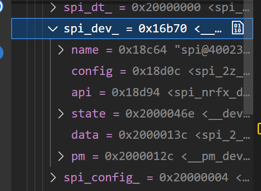
    this is the bus field returned by the devicetree macro.

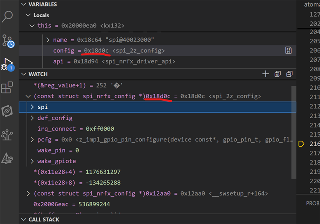
    the information is inside the config field but as you can see it is not reachable from at this point.
    in order to reach it I had to look deeper inside the call stack and see what the proper casting is:
    I found it is (const struct spi_nrfx_config *)
    so when I cast it, I can look inside it:

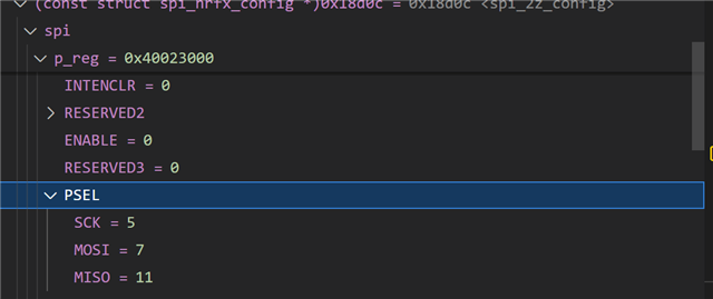
    if I open spi->p_reg->PSEL: 

    I can find the actual pin numbers I wrote in my device tree. 
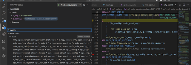
    when I went further in the call stack into the transcieve function, I found where the freqauncy, bit order, mode and irq find .
    I found these lines: 

    as you can see, in the call stack that starts at the transcieve function we got to these lines of configuration in which the orc, freqauncy an mode numbers go also into the p_reg.
    (the mode is not configurable through the device tree but through the operation variable that goes to the devicetree macro).
    so for conclusion I pretty much found the answers for my questions but I still have some followup questions:
    1. how can I control the orc and irq values? 
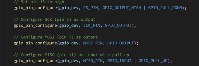
    2. how can I control the miso to be pull_up or pin_down. this is another change I saw in the old code that I didn't see mentioned in the samples based on the new SDK. The way it was don't in the old code is this: 


  • Hi,

    shlomots said:
    1. how can I control the orc and irq values? 

    .orc Can be set in devicetree. e.g. with a overlay like this:

    &spi0 {

        overrun-character = < 0xFF >;

    };

     irq can also be set in devicetree. But the default value is the recommended option.

    shlomots said:
    2. how can I control the miso to be pull_up or pin_down.

    Configuration on the pins is handled by the driver. You just need to set the pins you want to use, in the device tree.

    -Priyanka


  • Configuration on the pins is handled by the driver. You just need to set the pins you want to use, in the device tree.

    shouldnt these lines of code set miso for example as pull down?

Reply Children
No Data
Related