nRF52833 SAADC issue

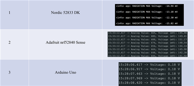
I have a photodiode, and under indoor lighting conditions, the reading on the oscilloscope is about 150mV. When I connect it to an Arduino Uno or Adafruit nRF52840 Sense, I can get a reading close to 150mV.

However, when I connect it to the nRF52840 DK, nRF52832 DK, or nRF52833 DK, using the official SDK's SAADC code, I cannot get the correct reading—the value stays negative. I need to use a flashlight to illuminate the photodiode for the ADC to respond and return the correct reading. Why is this happening? Could it be that the internal input impedance of the SAADC is much lower than that of the photodiode? I also noticed that Adafruit uses Nordic's SAADC, but they don't seem to have this issue. I look forward to your reply!
Parents
  • Hi,

    In order to provide advice I need to know more about how you are measuring. Can you share the ADV related code so that I see what you are doing? Also, what is the hardware setup, and what is the actual voltage you are measuring (is it 150 mV or something else)?

  • Thanks for your prompt reply! Below is my ADC code: 

    #define SAMPLES_IN_BUFFER 1
    volatile uint8_t state = 1;

    static const nrf_drv_timer_t m_timer = NRF_DRV_TIMER_INSTANCE(4);
    static nrf_saadc_value_t m_buffer_pool[2][SAMPLES_IN_BUFFER];
    static nrf_ppi_channel_t m_ppi_channel;
    static uint32_t m_adc_evt_counter;

    void timer_handler(nrf_timer_event_t event_type, void * p_context)
    {

    }


    void saadc_sampling_event_init(void)
    {
    ret_code_t err_code;

    err_code = nrf_drv_ppi_init();
    APP_ERROR_CHECK(err_code);

    nrf_drv_timer_config_t timer_cfg = NRF_DRV_TIMER_DEFAULT_CONFIG;
    timer_cfg.bit_width = NRF_TIMER_BIT_WIDTH_32;
    err_code = nrf_drv_timer_init(&m_timer, &timer_cfg, timer_handler);
    APP_ERROR_CHECK(err_code);

    /* setup m_timer for compare event every 400ms */
    uint32_t ticks = nrf_drv_timer_ms_to_ticks(&m_timer, 1);
    nrf_drv_timer_extended_compare(&m_timer,
    NRF_TIMER_CC_CHANNEL0,
    ticks,
    NRF_TIMER_SHORT_COMPARE0_CLEAR_MASK,
    false);
    nrf_drv_timer_enable(&m_timer);

    uint32_t timer_compare_event_addr = nrf_drv_timer_compare_event_address_get(&m_timer,
    NRF_TIMER_CC_CHANNEL0);
    uint32_t saadc_sample_task_addr = nrf_drv_saadc_sample_task_get();

    /* setup ppi channel so that timer compare event is triggering sample task in SAADC */
    err_code = nrf_drv_ppi_channel_alloc(&m_ppi_channel);
    APP_ERROR_CHECK(err_code);

    err_code = nrf_drv_ppi_channel_assign(m_ppi_channel,
    timer_compare_event_addr,
    saadc_sample_task_addr);
    APP_ERROR_CHECK(err_code);
    }


    void saadc_sampling_event_enable(void)
    {
    ret_code_t err_code = nrf_drv_ppi_channel_enable(m_ppi_channel);

    APP_ERROR_CHECK(err_code);
    }


    void saadc_callback(nrf_drv_saadc_evt_t const * p_event)
    {
    if (p_event->type == NRF_DRV_SAADC_EVT_DONE)
    {
    ret_code_t err_code;

    err_code = nrf_drv_saadc_buffer_convert(p_event->data.done.p_buffer, SAMPLES_IN_BUFFER);
    APP_ERROR_CHECK(err_code);

    int i;
    //NRF_LOG_INFO("ADC event number: %d", (int)m_adc_evt_counter);

    for (i = 0; i < SAMPLES_IN_BUFFER; i++)
    {

    NRF_LOG_INFO("RADIATION Voltage: " NRF_LOG_FLOAT_MARKER " mV", NRF_LOG_FLOAT((p_event->data.done.p_buffer[i] * 3.6f * 1000) / 16384));

    }
    //m_adc_evt_counter++;
    }
    }


    void saadc_init(void)
    {
    ret_code_t err_code;
    nrf_saadc_channel_config_t channel_config =
    NRF_DRV_SAADC_DEFAULT_CHANNEL_CONFIG_SE(NRF_SAADC_INPUT_AIN3);

    err_code = nrf_drv_saadc_init(NULL, saadc_callback);
    APP_ERROR_CHECK(err_code);

    err_code = nrf_drv_saadc_channel_init(0, &channel_config);
    APP_ERROR_CHECK(err_code);

    err_code = nrf_drv_saadc_buffer_convert(m_buffer_pool[0], SAMPLES_IN_BUFFER);
    APP_ERROR_CHECK(err_code);

    err_code = nrf_drv_saadc_buffer_convert(m_buffer_pool[1], SAMPLES_IN_BUFFER);
    APP_ERROR_CHECK(err_code);

    }

    I am using saadc sample code to get the ADC readout and print it out. All the set up is as follows:

    #define NRFX_SAADC_DEFAULT_CHANNEL_CONFIG_SE(PIN_P) \
    { \
    .resistor_p = NRF_SAADC_RESISTOR_DISABLED, \
    .resistor_n = NRF_SAADC_RESISTOR_DISABLED, \
    .gain = NRF_SAADC_GAIN1_6, \
    .reference = NRF_SAADC_REFERENCE_INTERNAL, \
    .acq_time = NRF_SAADC_ACQTIME_3US, \
    .mode = NRF_SAADC_MODE_SINGLE_ENDED, \
    .burst = NRF_SAADC_BURST_DISABLED, \
    .pin_p = (nrf_saadc_input_t)(PIN_P), \
    .pin_n = NRF_SAADC_INPUT_DISABLED \
    }

    #define NRFX_SAADC_DEFAULT_CONFIG \
    { \
    .resolution =  14 bit \
    .oversample = disable
    .interrupt_priority = 6
    .low_power_mode =0 

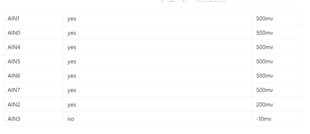
    I am very confused that when I connect a phtodiode with 150mv to the ADC, the readout will be negative number. When I give a strong light on the diode it will go up to 300mv, and then I can get the correct data from ADC with 300mv. It seems that the ADC has a threshold above which it will start Slight smile

  • Yes, exactly! The ADC works correctly in a high-light environment and can return the correct voltage value to me (consistent with the voltage read by the oscilloscope). However, in a dim environment, the oscilloscope reads 150mv and the ADC reads a negative number.

  • I see. In that case, which voltage to you read with the ADC? I see you are not performing offset calibration, which could be relevatn (though 150 mV is a lot in this regard). But I suggest you implement that first, using nrf_drv_saadc_calibrate_offset(). You can see an example of that here.

  • thank you so much for your information! I will try it as soon as possible: )

  • Hi Einar,

    I have tried the calibration code but still got the same result. Some interesting observation is that when I connected GND to the AIN pin, the readout will still be negative number and being unstable. Could you please give me some advice?

  • Hi,

    I am not sure what is causing this, so we need to look a bit futher:

    1. Can you try to print the raw int value you get and not only the number after you convert to float and do multiplication and division?
    2. Can you show how you ahve connected it to the SoC in hardware (a simple schematic or similar)?
    3. Can you double check and let me know which pin it is connected to? (Could it be that it is not connected to the right pin so that you are measuring a floating input)?
Reply
  • Hi,

    I am not sure what is causing this, so we need to look a bit futher:

    1. Can you try to print the raw int value you get and not only the number after you convert to float and do multiplication and division?
    2. Can you show how you ahve connected it to the SoC in hardware (a simple schematic or similar)?
    3. Can you double check and let me know which pin it is connected to? (Could it be that it is not connected to the right pin so that you are measuring a floating input)?
Children
Related