Antenna for Small USB Receiver

Hi,

We are designing a USB Receiver based off the Nordic Proprietary Radio + ESB.

Do you have any reference designs for a PCB antenna which must be as small as possible?

The current meander PCB antenna from the design reference is 10x5mm which is small, but is there an antenna that could have more meanders to reduce the footprint size even further?

As the 1/4 wavelength for 2.4GHz is around 30mm, does this mean we could have many meanders as long as the total length is around 30mm?

Regards,

Parents
  • Hello Adrian,
    I assume you are referring to the antenna on the nRF52840 dongle: https://www.nordicsemi.com/Products/Development-hardware/nRF52840-Dongle
    We don't really have anything PCB printed that is smaller. It's a trade of in complexity, bandwidth and space. You can make it more compact, but you will most likely have to make it slightly longer to compensate for the increased coupling between the meanders. In most cases where customers need even further reduction, they've gone with a SMD antenna and added three components to tune it in application. They are usually smaller in volume and board space, but of course, they come at a cost. You can try to design a more compact antenna based on the dongle, but we don't have any ready made alternatives that are smaller in board space.
    Are you constrained to some type of PCB shape? 
    Best regards
    Asbjørn
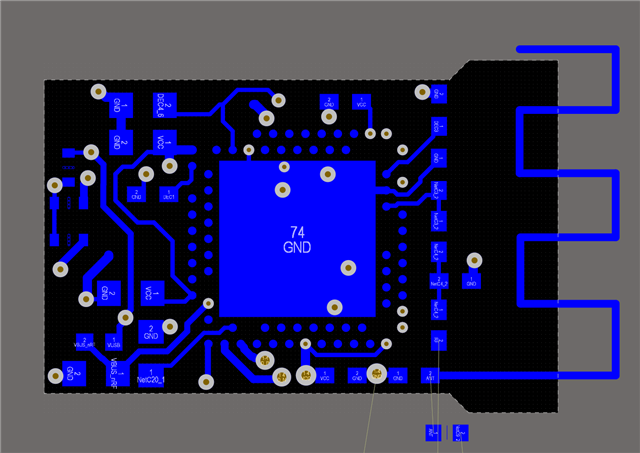
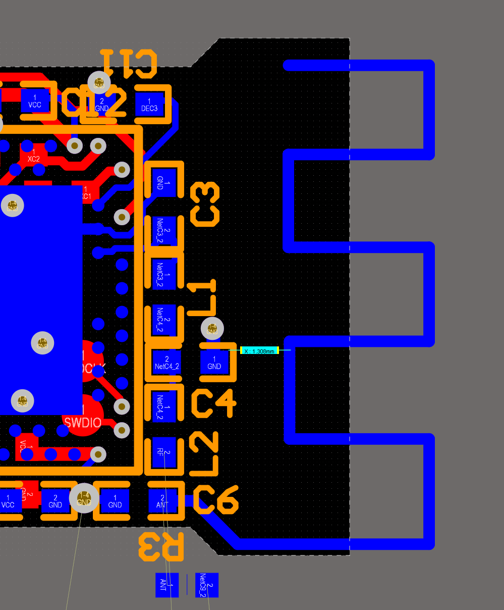
  • This is the Dongle Antenna copy pasted verbatim into our design. What flexibility do we have around changing various dimensions?

    Would it be just a case of making sure we keep the meandering part about 1.8mm away from the ground plane?

    As our PCB stack up does not match that of the Dongle, there'd still have to be some component tuning anyway.

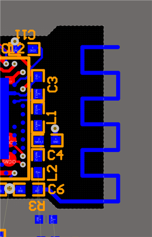
    Or could we add another meander like so to allow us to narrow the footprint?

Reply
  • This is the Dongle Antenna copy pasted verbatim into our design. What flexibility do we have around changing various dimensions?

    Would it be just a case of making sure we keep the meandering part about 1.8mm away from the ground plane?

    As our PCB stack up does not match that of the Dongle, there'd still have to be some component tuning anyway.

    Or could we add another meander like so to allow us to narrow the footprint?

Children
  • Hello Adrian,

    You can adjust all the parameters you want to try and make it fit. In general though:
    1. The overall length should be approximately ¼ of the wavelength as a rule of thumb.
    2. The width of the trace used for the antenna can be used to adjust bandwidth of the antenna. It shouldn't be wider than it need though.
    3. If you move the meanders closer together, you'll increase the capacitance between them, change the effectiveness of the antenna and probably need to extend the length of the antenna, but it could still be ok for your application performance wise.
    4. Moving the antenna closer towards the chip will also increase the capacitance in the antenna and extra length might be needed. The distance and direction to the ground plane under the chip and PCB affects the radiation pattern and effectiveness of the antenna as well.
    5. If you make the meanders smaller that's fine, but yeah, keep an eye one the overall length of the antenna trace.
    6. The more complex shape of the antenna, usually he radiation pattern becomes equally messy, but might still be ok.
    7. Add a bit of extra length to a trial version of the PCB. You can tune the length on PCB by cutting off length as long as you have a bit extra to cut off.
    8. The tuning of the antenna is what is important, if you can find and make a pattern that is long enough, then try to tune it with length adjustments and possibly components as well. By tuning it in place you might get an antenna the works just fine for your application. It will never be perfect, but it might be ok for your case.

    Do you have some SW to simulate antenna in?


    Best regards
    Asbjørn

Related