Hello,
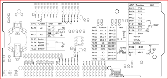
My team and I are working on a project where we need our nRF5340 to send data via UART from the board to a RaspberryPI. We designed a custom PCB with the chip and connected the UART pins 00 and 01 as RX and TX respectively. To test that we could switch the UART pins from their default value of 20 and 22, we are using the nRF5340dk board and we are running into configuration problems.
Initially, we adjusted the .dts files for the application core to change the uart0_default values to our new TX & RX values, however, after reading this forum: https://devzone.nordicsemi.com/f/nordic-q-a/112174/uart-configuration-for-nrf5340dk-controller-and-nrf5340-audio-dk-host, it is clear that we are not meant to touch the .dts files.
Next, we added to our overlay file, redefining the uart0 struct and following the general structure highlighted in the above forum. I have attached the overlay file below:
/ {
	chosen {
		zephyr,bt-uart = &uart0;
	};
};

&i2c1 {
	status = "okay";
	compatible = "nordic,nrf-twim";
	label = "I2C_1";
	pinctrl-0 = <&i2c1_default>;
	pinctrl-1 = <&i2c1_sleep>;
	pinctrl-names = "default", "sleep";
	clock-frequency = <400000>;

};

&uart0 {
	status = "okay";
	label = "UART_0";
	current-speed = <115200>;
	pinctrl-0 = <&uart0_default>;
	pinctrl-1 = <&uart0_sleep>;
	pinctrl-names = "default", "sleep";
};

&pinctrl {

	uart0_default: uart0_default {
		group1 {
			psels = <NRF_PSEL(UART_TX, 1, 1)>,
				<NRF_PSEL(UART_RTS, 0, 11)>;
		};
		group2 {
			psels = <NRF_PSEL(UART_RX, 1, 0)>,
				<NRF_PSEL(UART_CTS, 0, 10)>;
			bias-pull-up;
		};
	};

	uart0_sleep: uart0_sleep {
		group1 {
			psels = <NRF_PSEL(UART_TX, 1, 1)>,
				<NRF_PSEL(UART_RX, 1, 0)>,
				<NRF_PSEL(UART_RTS, 0, 11)>,
				<NRF_PSEL(UART_CTS, 0, 10)>;
			low-power-enable;
		};
	};

	i2c1_default: i2c1_default{
		group1 {
			psels = <NRF_PSEL(TWIM_SDA, 0, 5)>, //was 7 sda and 6 scl
				<NRF_PSEL(TWIM_SCL, 0, 4)>;
		};
	};

	i2c1_sleep: i2c1_sleep{
		group1 {
			psels = <NRF_PSEL(TWIM_SDA, 0, 5)>,
				<NRF_PSEL(TWIM_SCL, 0, 4)>;
			low-power-enable;
		};
	};

};

&gpio1 {
	status = "okay";
	label = "GPIO_1";
};
The issue is when we use a logic analyzer, the TX pin is not sending any data. When we comment out our redefinition of uart0 in the overlay file, the dk board successfully sends data out of the default 22/20 pins that are defined in the .dts file. We were wondering if we have gone about reconfiguring the UART correctly. Are there any steps we are missing?
I found another forum that talks about binding the UART lines (https://devzone.nordicsemi.com/f/nordic-q-a/77130/configuring-multiple-uarts-on-nrf5340dk-plus-other-serial-interfaces), however, since this wasn't done explicitly for the uart0 struct, we aren't sure where to do this except in main as follows:
// ---- Main Function ----
const struct device * uart0;
int main(void)
{
  uart0 = device_get_binding("UART_0");
  if(!uart0){
    printk("Error: Could not get UART0 Device Tree Ref\n");
    return 1;
  }

	// ---- BLE Initialization ----

	static struct k_work button_work;
	int err = -1;

	printk("Initializing...\n");

	if (IS_ENABLED(CONFIG_HWINFO)) {
	...
This is part of our project config that we added (excluding the BLE stuff). Not sure if this would help.
# IMU configs
CONFIG_GPIO=y
CONFIG_STDOUT_CONSOLE=y
CONFIG_PRINTK=y
CONFIG_I2C=y
# CONFIG_LOG=y

CONFIG_TFM_SECURE_UART=n
CONFIG_TFM_LOG_LEVEL_SILENCE=y

# UART configs
CONFIG_SERIAL=y
CONFIG_UART_ASYNC_API=y
CONFIG_LOG_MODE_IMMEDIATE=y
Any help would be appreciated!


