CR2032 Coin Cell Battery Monitoring Circuit using nRF52840

Hello,

I am designing a battery monitoring circuit for a 3.0V CR2032 coin cell using the nRF52840, and had some questions. I am following the battery monitoring circuit used on the Thingy52 DK as a reference:
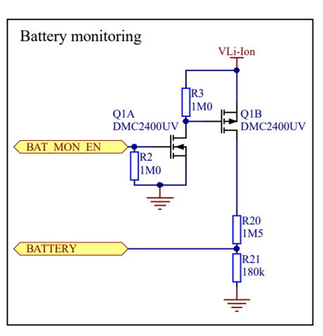
I understand how most of this circuit works, except for the values chosen for R20 and R21. How should I go about choosing these values? From the following thread, it sounds like we want to have this voltage divider so the battery voltage can be divided down to the bandgap voltage:  ADC to measure battery voltage 

I have been unable to find the bandgap voltage for the nRF52840 from the data sheet, and would like to know a bit more about the bandgap voltage and why it is useful.

Another concern I have is measuring the battery voltage as it drifts. Over time, the battery will obviously deplete (which is why we want to monitor it), and I would like to know how this will impact our ADC readings as the reference voltage will be changing.

I am open to any other suggestions regarding this problem.

Thanks in advance!

Parents
  • First no external circuit is required to measure the battery voltage if using a CR2032 as the coin cell 3.4V drives the nRF VDD directly without using an external regulator; there is an internal VDD measurement option on the SAADC for this. Next the battery voltage will tell you almost nothing about remaining capacity of a Lithium coin cell due to internal cell resistance; applying a brief load and measuring voltage before and after the load is a much better fuel gauge for a coin cell.

    For a detailed explanation and some coin cell fuel gauge code see my comments here

  • Hi  , thanks for your suggestion.

    I took a look at the coin cell fuel gauge post you referred to and still have some questions:

    1) I am still unclear on how the internal VDD measurement should be set up. Is there a need to connect the positive terminal of the battery to an analog input pin?

    2) How can measuring the voltage drop between before/after a Tx pulse be used to indicate battery life percentage to a user? In our application we send pressure data from a sensor over BLE and want to send "battery percentage" along with the pressure data. If we get the voltage drop between the start/end of transmission how can we relate this drop to the state of charge of the battery as a battery life percentage.

    3) I am using a 100uF ceramic decoupling capacitor for the coin cell. Is this sufficient bulk capacitance if we want to transmit every 10 seconds when the device is powered on? 

    4) Out of curiosity, why does the Thingy52 use this external circuitry to measure the battery voltage? Are external circuits such as the one I posted typically not good indicators of state of charge for a battery?

Reply
  • Hi  , thanks for your suggestion.

    I took a look at the coin cell fuel gauge post you referred to and still have some questions:

    1) I am still unclear on how the internal VDD measurement should be set up. Is there a need to connect the positive terminal of the battery to an analog input pin?

    2) How can measuring the voltage drop between before/after a Tx pulse be used to indicate battery life percentage to a user? In our application we send pressure data from a sensor over BLE and want to send "battery percentage" along with the pressure data. If we get the voltage drop between the start/end of transmission how can we relate this drop to the state of charge of the battery as a battery life percentage.

    3) I am using a 100uF ceramic decoupling capacitor for the coin cell. Is this sufficient bulk capacitance if we want to transmit every 10 seconds when the device is powered on? 

    4) Out of curiosity, why does the Thingy52 use this external circuitry to measure the battery voltage? Are external circuits such as the one I posted typically not good indicators of state of charge for a battery?

Children
  • I'll give some quick responses, then update later with a code example to try to explain better.

    1. No need to connect the positive terminal battery to an analog input pin: VDD (the battery) is already connected internally to an SAADC input
    2. A typical battery has to be calibrated in terms of voltage droop for a given current pulse over the expected life of the typical battery; this then becomes a look-up table where droop over the battery lifetime increases as remaining capacity reduces and hence acts as a reasonable fuel gauge
    3. 100uF is the minimum, 150uF is better. The capacitor voltage rating must be at least double VDD to avoid derating the capacitance. 6.3V rating is ok, 10V rating is better
    4. A rechargeable Lithium-Ion battery has a voltage (4.2V) which exceeds the 3.6V maximum voltage of the nRF52 input pin whereas a CR2032 has a maximum voltage of 3.4V which is ok as less than 3.6V so no voltage divisor is required

    Here the coin cell voltage (VDD) is measured before and after the pressure is sent over BLE and generates a "droop" voltage of 466mV; this droop gets larger as the battery slowly becomes exhausted over time as the battery internal impedance increases. Send the last droop measurement with the current pressure measurement.

    // Coin Cell After Rest: 2716mV, After Tx Pulse: 2250mV, Droop:  466mV

    Algorithm:

    sleep & periodically wakeup
     // Time to transmit pressure
     {
       // Read battery voltage after sleep before BLE activity
       BatteryVoltsA = GetBatteryVoltage();
       // Send pressure via BLE - causes increased current consumption for transmit packet
       SendPressureAndLastDroop();
       // After transmit packet read battery voltage, it will be lower
       BatteryVoltsB = GetBatteryVoltage();
       LastDroop = BatteryVoltsB - BatteryVoltsA;
     }

Related