Hello,
I have a Insight ISP4520 SIp which include a nRF52832 chip and a SX1261 for Lora radio https://www.insightsip.com/products/combo-smart-modules/isp4520
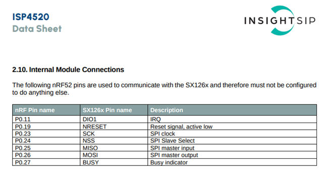
The internal connection of the module are available in this pdf page 13 https://www.insightsip.com/fichiers_insightsip/pdf/ble/ISP4520/isp_lora_DS4520.pdf

I have sucessfully done the nordic academy beginner, BLE and intermediate courses (very interesting) on this chip.
Now I try to make the SX1261 working using this sample https://github.com/zephyrproject-rtos/zephyr/tree/main/samples/drivers/lora/send without success for the moment.
I got this log when running the sample :
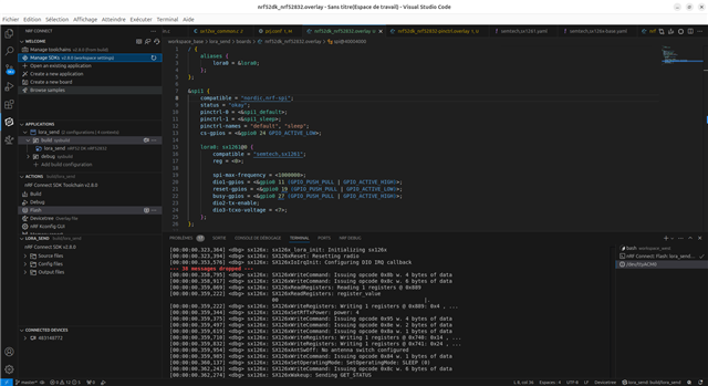
[00:00:00.323,364] <dbg> sx126x: sx126x_lora_init: Initializing sx126x
[00:00:00.323,394] <dbg> sx126x: SX126xReset: Resetting radio
[00:00:00.353,576] <dbg> sx126x: SX126xIoIrqInit: Configuring DIO IRQ callback
--- 38 messages dropped ---
[00:00:00.358,795] <dbg> sx126x: SX126xWriteCommand: Issuing opcode 0x8b w. 4 bytes of data
[00:00:00.358,917] <dbg> sx126x: SX126xWriteCommand: Issuing opcode 0x8c w. 6 bytes of data
[00:00:00.359,069] <dbg> sx126x: SX126xReadRegisters: Reading 1 registers @ 0x889
[00:00:00.359,222] <dbg> sx126x: SX126xReadRegisters: register_value
                                 00                                               |.
[00:00:00.359,222] <dbg> sx126x: SX126xWriteRegisters: Writing 1 registers @ 0x889: 0x4 , ...
[00:00:00.359,344] <dbg> sx126x: SX126xSetRfTxPower: power: 4
[00:00:00.359,375] <dbg> sx126x: SX126xWriteCommand: Issuing opcode 0x95 w. 4 bytes of data
[00:00:00.359,497] <dbg> sx126x: SX126xWriteCommand: Issuing opcode 0x8e w. 2 bytes of data
[00:00:00.359,619] <dbg> sx126x: SX126xWriteCommand: Issuing opcode 0x8a w. 1 bytes of data
[00:00:00.359,710] <dbg> sx126x: SX126xWriteRegisters: Writing 1 registers @ 0x740: 0x14 , ...
[00:00:00.359,832] <dbg> sx126x: SX126xWriteRegisters: Writing 1 registers @ 0x741: 0x24 , ...
[00:00:00.359,954] <dbg> sx126x: SX126xAntSwOff: No antenna switch configured
[00:00:00.359,985] <dbg> sx126x: SX126xWriteCommand: Issuing opcode 0x84 w. 1 bytes of data
[00:00:00.360,137] <dbg> sx126x: SX126xSetOperatingMode: SetOperatingMode: SLEEP (0)
[00:00:00.362,243] <dbg> sx126x: SX126xWriteCommand: Issuing opcode 0x8c w. 6 bytes of data
[00:00:00.362,274] <dbg> sx126x: SX126xWakeup: Sending GET_STATUS
[00:00:00.362,335] <dbg> sx126x: SX126xWakeup: Waiting for device...
[00:00:00.362,365] <dbg> sx126x: SX126xWakeup: Device ready
[00:00:00.362,396] <dbg> sx126x: SX126xAntSwOn: No antenna switch configured
[00:00:00.362,548] <dbg> sx126x: SX126xWriteCommand: Issuing opcode 0x8 w. 8 bytes of data
[00:00:00.362,701] <dbg> sx126x: SX126xWriteCommand: Issuing opcode 0x8c w. 6 bytes of data
[00:00:00.362,854] <dbg> sx126x: SX126xWriteBuffer: Writing buffers @ 0x0 (10 bytes)
[00:00:00.363,037] <dbg> sx126x: SX126xSetOperatingMode: SetOperatingMode: TX (4)
[00:00:00.363,067] <dbg> sx126x: SX126xWriteCommand: Issuing opcode 0x83 w. 3 bytes of data
[00:00:00.363,220] <dbg> sx12xx_common: sx12xx_lora_send: Expected air time of 10 bytes = 289ms
[00:00:00.941,314] <err> sx12xx_common: Packet transmission failed!
[00:00:00.941,345] <dbg> sx126x: SX126xAntSwOff: No antenna switch configured
[00:00:00.941,375] <dbg> sx126x: SX126xWriteCommand: Issuing opcode 0x84 w. 1 bytes of data
[00:00:00.941,497] <dbg> sx126x: SX126xSetOperatingMode: SetOperatingMode: SLEEP (0)
[00:00:00.943,572] <err> lora_send: LoRa send failed
Here is the device tree I tried to configure for the Lora0 device :
/ {
    aliases {
        lora0 = &lora0;
    };
};

&spi1 {
    compatible = "nordic,nrf-spi";
    status = "okay";
    pinctrl-0 = <&spi1_default>;
    pinctrl-1 = <&spi1_sleep>;
    pinctrl-names = "default", "sleep";
    cs-gpios = <&gpio0 24 GPIO_ACTIVE_LOW>;

    lora0: sx1261@0 {
    	compatible = "semtech,sx1261";
    	reg = <0>;

        spi-max-frequency = <1000000>;
        dio1-gpios = <&gpio0 11 (GPIO_PUSH_PULL | GPIO_ACTIVE_HIGH)>;
        reset-gpios = <&gpio0 19 (GPIO_PUSH_PULL | GPIO_ACTIVE_LOW)>;
        busy-gpios = <&gpio0 27 (GPIO_PUSH_PULL | GPIO_ACTIVE_HIGH)>;
        dio2-tx-enable;
        dio3-tcxo-voltage = <7>;
    };
};
And the pinctrl :
&pinctrl {
    spi1_default: spi1_default {
        group1 {
            psels = <NRF_PSEL(SPIM_SCK, 0, 23)>,
                    <NRF_PSEL(SPIM_MOSI, 0, 26)>,
                    <NRF_PSEL(SPIM_MISO, 0, 25)>;
        };
    };
    spi1_sleep: spi1_sleep {
        group1 {
            psels = <NRF_PSEL(SPIM_SCK, 0, 23)>,
                    <NRF_PSEL(SPIM_MOSI, 0, 26)>,
                    <NRF_PSEL(SPIM_MISO, 0, 25)>;
            low-power-enable;
        };
    };
};
What is wrong with my device tree configuration ? And why I can use the the SPI0 ?
Many thanks by adavance and feel free to ask more details if needed.

