Hi,
I've looked at the example codes provided by Martin in these two topics for communicating to a MPU6050 through TWI:
1- devzone.nordicsemi.com/.../ (uses SDK 9) 2- devzone.nordicsemi.com/.../ (uses SDK 10)
Just for others to know: The first one is just a TWI example, and the second one has a set of functions added for MPU9150/MPU6050. I found the only difference between SDK 9 and 10 in the nrf_drv_twi_init function, which needs 3 parameters in SDK 9 and 4 parameters in SDK 10. Also, I paid attention to TWI instance used in NRF_DRV_TWI_INSTANCE, and enabled it in nrf_drv_config.
I'm in process of trouble shooting this and any comments can help. Here are what I observed by using the codes above in my project on a PCA20006 with 3rd revision IC and SDK 9. Similar to 2, I only use twi_init(), mpu_init() and then just a couple of readings.
1- Without connecting the MP board, I added a blinking LED code in mpu9150_twi_event_handler which is called by twi_handler. This is added under "case NRF_DRV_TWI_ERROR". As there is no device on TWI, program goes to this error case and LED blinks.
2- When connecting the MPU board, the program doesn't go to the error case at all, and also exactly after using mpu_init(), the current of MPU board goes from 0 to 3~4 mA. So, I thought the TWI is working. BUT,
3- I added an IO pin toggle for 10usec, under "case NRF_DRV_TWI_TX_DONE". Similar to the TWI example by Martin I expected that after a successful TX, it should go to that case and toggle the pin. But, this doesn't happen + when I monitor the SCL and SDA pins it seems that they are always "HIGH".
From one hand, it seems that two boards are actually communicating as compared to "no MPU case", the code never goes to the error case. On the other hand it doesn't go to TX_DONE case either and it seems that the pins are not changing.
Any comments?
BTW, SDA and SCL lines are pulled up in MPU6050 board to its VLOGIC=3V by 2K resistors.
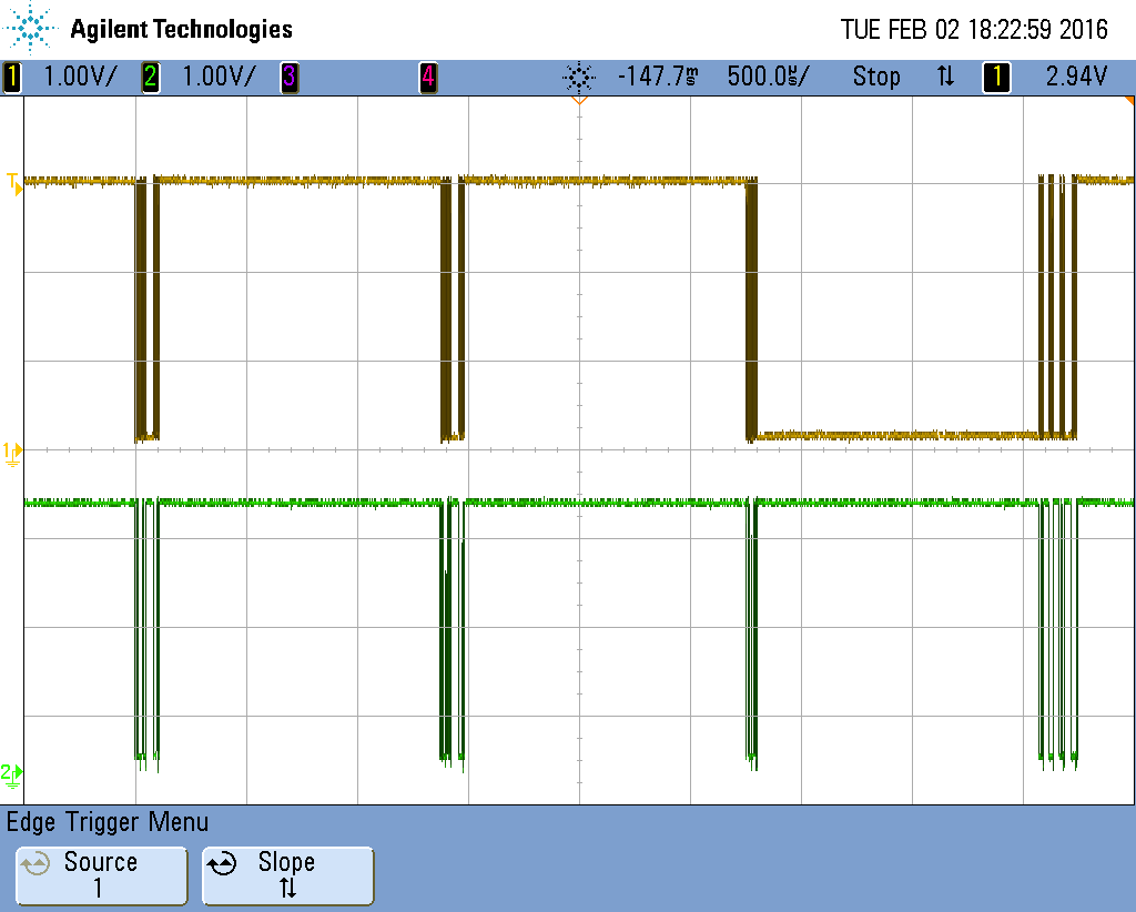
Update 1 - Oscilloscope screen shot with MPU9150_TWI_TIMEOUT = 5000 - See Comments for more information

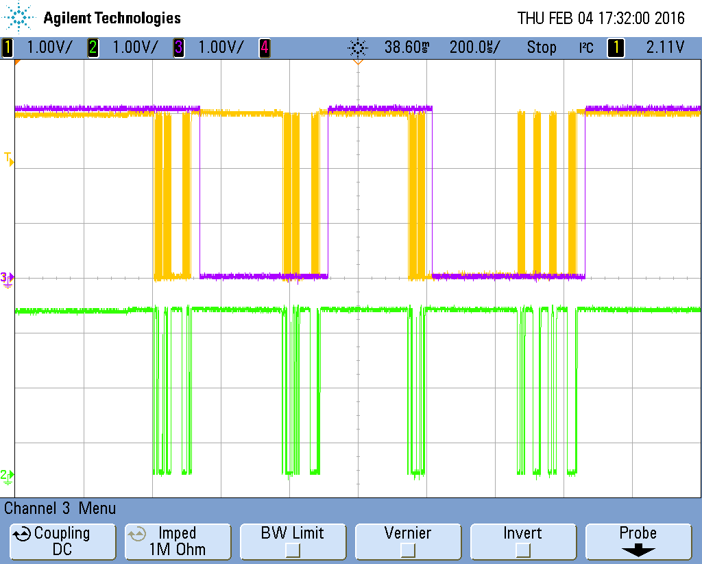
Update 2 - Screen shot with MPU9150_TWI_TIMEOUT = 1000 with an IO pin toggling after each NRF_DRV_TWI_RX_DONE event

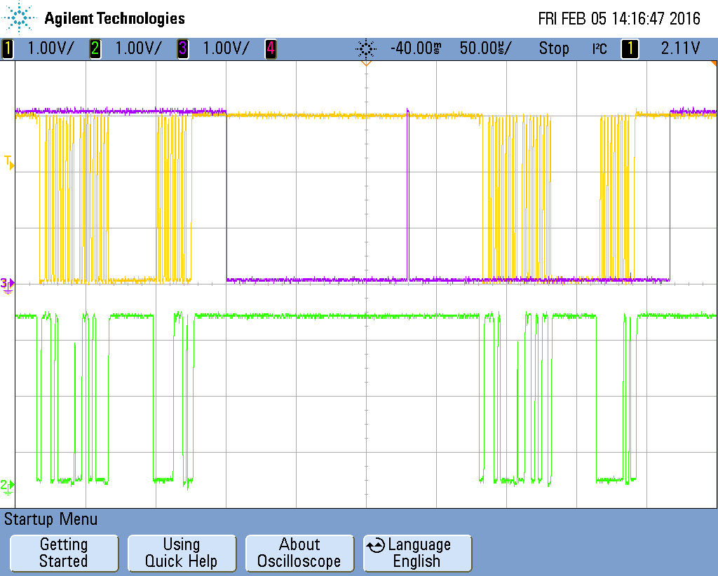
Update 3 - Screen shot with MPU9150_TWI_TIMEOUT = 750 with an IO pin toggling after each NRF_DRV_TWI_RX_DONE event + IO pin toggle after the while loop + conditional toggle based on twi_tx_done


