Dear Team,
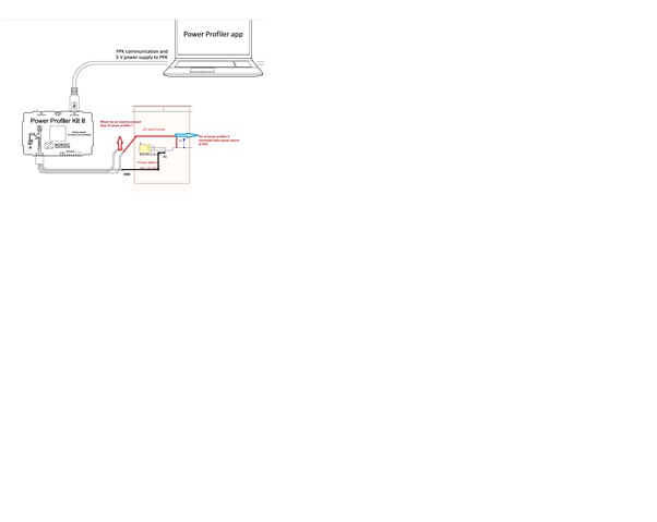
We want to use the Power Profiler II as our ammeter to measure the current of our newly designed PCBA. However, we’re uncertain about the proper connections for our setup based on the illustration in the manual (page 11, Figure 6 Link: docs.nordicsemi.com/.../PPK_user_guide_Intro.html), which depicts an nRF board. It suggests using an external power source for the DUT and connecting the Vin pin to the series line.
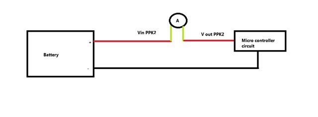
In our setup:
- Vin is connected to the power line.
- GND is connected to ground.
However, we’re unsure about the correct connection for the Vout pin. Could you please clarify where it should be connected?
Additionally, could you advise whether we should select Source Meter Mode or Ammeter Mode in the application for this configuration? Your guidance will be highly appreciated!


