nrf9161 custom board - sim card problems - CEREG:90

Hi.

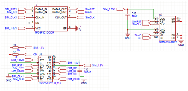
I have a custom board with a NRF9161. The nrf91's LTE block connects to the sim holder through a NX3DV2567HR switch and an TPD3F303DQDR ESD protection. 

I'm using a very simple firmware just to confirm if all is working but I always get a "CEREG:90" response. 

I've checked with an oscilloscope that the nrf9161 is sending the SIM_CLK signal at the beginning of the connection, but I never see any changes in the SIM_VCC pin (always at 0V). A stable 1.8V bus is feeding the VDD_GPIO. I've made this test in two different boards and got the same result.

Can anyone suggest any good strategy to debug and solve this?

Thank you all in advance.  

Parents
  • Hello Ricardo,
    are you able to share the details on how you have implemented the SIM interface and component setup/schematic?
    The CEREG:90 response means:
    This would be as expected if the VDD_SIM is always 0V. Is there a short on the board? Could you probe on the VCC_SIM and GND and see if for some reason there's a short?
    Best regards
    Asbjørn
  • Thank you so much for your answer.

    I've checked that already, and there is no short circuit to the ground on the VCC_SIM pin. I imagined that the cereg:90 is due to the lack of power to the card-related components.

    That part of the schematic is as follows (CD pin is at GND when card is inserted). Independently from having or not having installed these 3 components in the board, I'm unable to get the VCC_SIM 1.8V at the supply pins of these 3 components. This code is working in the 9161DK.

    I considered soldering issues, but I have the same behaviour in 2 units of the custom board with the same result. I also don't know how relevant it might be, but the modem firmware is updated to the latest version.

    Thanks again in advance for other ideas you might have.

  • Hello Ricardo,
    If I understand you correctly you are not able to measure or detect 1.8V on any of the 1V8 pins described in the schematic snipped you attahced? 
    What is the voltage on either side of the R7 resistor related to Card Discovery (CD) close the the NXP filter? Is it high enough to pull the CD to HIGH? 
    The voltage on C12 cap, is it the same 0V as you see on C13?
    I'm not sure if you've added any other component between the SIM_VDD from the nRF9161 SiP, but are you able to separate the SIM_VDD from the NX3DV input and see if that helps, jus to confirm that the SIM_VDD is able to go up to 1.8V. 
    Best regards
    Asbjørn
Reply
  • Hello Ricardo,
    If I understand you correctly you are not able to measure or detect 1.8V on any of the 1V8 pins described in the schematic snipped you attahced? 
    What is the voltage on either side of the R7 resistor related to Card Discovery (CD) close the the NXP filter? Is it high enough to pull the CD to HIGH? 
    The voltage on C12 cap, is it the same 0V as you see on C13?
    I'm not sure if you've added any other component between the SIM_VDD from the nRF9161 SiP, but are you able to separate the SIM_VDD from the NX3DV input and see if that helps, jus to confirm that the SIM_VDD is able to go up to 1.8V. 
    Best regards
    Asbjørn
Children
  • Hi again, Asbjørn

    Yes, no 1.8V anywhere in this area of the circuit.

     Cap C12 and C13 are 0V. I've removed the NXP to be sure that it's not influencing the 1.8V output from the SoC. I still get 0V. I had already reduced the value of the pull-up resistor to ensure the 1.8V but, again, always 0V. Voltage on R7 is always that value too on either side. The trace going from the SoC to the NXP VCC is uninterrupted by any component, going through a via to the bottom layer right after the NRF pin and coming back to the top layer again near the NXP.

    Thanks!

    Regards

    P.S: - I'm using v2.6.1 SDK and toolchain. Might this have anything to do with it, given I updated the modem firmware?

  • Hi Ricardo,
    the absence of voltage from the SIM_VDD output on the nRF9161 for your SIM_1V8 input for the NXP chip indicates that there might be something wrong before that location. 
    Do you happen to have a nRF9161 DK available? Does your FW and modem FW work on that kit?
    How was the nRF9161 SiP soldered to your custom board? How close to the nRF9161 on your custom board are you able to probe with the scope you have? Are you able to find the SIM_VDD output pin from the SiP and probe on that to see if there's some slight changes to the voltage at startup that might indicate that there is a short under the SiP? The same probing could be done on all the SIM  intercae pins as close to the nRF9161 as possible during satrtup and during enabling of the SIM interface to see if there as some very short signals or behaviour on them.
    Regarding the modem FW and SDK version? Are you able to build an example with a later version of NCS and try it on your board to see if that makes a differenc in your case. I'm not aware of any changes to the SDK that would do this, but you never know in some instances.
    Best regards
    Asbjørn
  • Hi Asbjørn,

    I’m sorry for the late reply; I was out for a few days and then working on other things and this matter got paused Neutral face My answers are inline:


    the absence of voltage from the SIM_VDD output on the nRF9161 for your SIM_1V8 input for the NXP chip indicates that there might be something wrong before that location. 

    Do you happen to have a nRF9161 DK available? Does your FW and modem FW work on that kit?

    - Yes, i have tried the firmware in the DK (with the same updated Modem Firmware) and I get the 1.8V .

    How was the nRF9161 SiP soldered to your custom board?

    -Manually, using a hot bed. I can accept that could be a bad solder on this specific pin but I get the same reaction in the second board.

    How close to the nRF9161 on your custom board are you able to probe with the scope you have?

    • I have the track and a via ~ 1mm away from the nrf9161. I’m only unable to test under the nrf9161 but I’m very close to the pin.

    Are you able to find the SIM_VDD output pin from the SiP and probe on that to see if there's some slight changes to the voltage at startup that might indicate that there is a short under the SiP?

    • I’ve had the Oscilloscope there and can’t find any fluctuations (even very small) even at startup. I have tested the firmware on a second custom board as I think I’ve said before but I haven’t tested this oscillation in that second one.

     The same probing could be done on all the SIM  intercae pins as close to the nRF9161 as possible during satrtup and during enabling of the SIM interface to see if there as some very short signals or behaviour on them.

    • I’ve checked the clock signal and is ok, but I haven’t checked the remaining. I will test that.

    Regarding the modem FW and SDK version? Are you able to build an example with a later version of NCS and try it on your board to see if that makes a differenc in your case. I'm not aware of any changes to the SDK that would do this, but you never know in some instances.

    - This I still need to try this as i will have to adapt the board definitions (2.6.1 -> 2.80 version).

    Regards,

  • Hi, Ricardo.

    Apologies for the delayed response here. Asbjørn is currently out of office due to the holidays.

    Would you be able to upload a PDF containing your entire schematic and the Gerber files so we can have a look at your layout as well?

    Best regards,
    Mathias

Related