MPSL Assert Error and Arch_Except Reason 3 error when using BLE

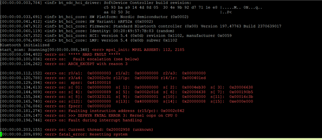
Hello, I have a custom board that was designed for me, but based off of the Acconeer XM126.  It is very similar with a few minor differences.  The person who designed it has bailed and is no longer reachable.  I am a mechanical engineer with limited coding and electrical knowledge.  I have had to stumble my way through.  There were multiple errors with the board that I have had to fix so far including the wrong HF crystal.  He originally had a 24mhz crystal and I had it replaced with a 32 and proper load capacitance.  The other issue is that he added a push button for BLE pairing.  It appears he meant to send 1.8v to pin y23 when the button is pushed.  It is incorrect and is sending 1.8v to y23 all the time.  I don't know if that could be an issue or not.  I'm not sure where the call out would be for what to do with that pin when it was getting the voltage.  I have searched his source and header files.  The board works with the radar sensor when I flash it with normal distance detecting programs.  However, when I load my program or any example program that uses BLE it gives me the errors I have attached.  MPSL Assert 112, 2185 and Arch except reason 3.  Also, zephyr fatal error 3: Kernel oops on cpu 0, fault during interrupt handling.  This is the last piece of the puzzle for me.  Does anyone have any idea what this might be?  Please remember I am limited in my knowledge.  I have already spent thousands to get here, so I am trying to solve this on my own.  Thanks.
  • Hi there Mike, 

    Can you share some more info here, its a bit difficult to get in to all the aspects whitout having an overview of the schematic. 

    But if the designers bailed and things have not been updated properly, but you have had to fix the physical board then things can be a bit difficult to debug. 


    The board works with the radar sensor when I flash it with normal distance detecting programs.  However, when I load my program or any example program that uses BLE it gives me the errors I have attached. 

    So looks like most of the HW is ok, but it would be good to see if only a basic sample with BLE would work. 

    Have you tested a simple application like Peripheral UART, https://github.com/nrfconnect/sdk-nrf/tree/main/samples/bluetooth/peripheral_uart.


    Also feel free to ask about anything and also know that we will help with review schematic and Hardware layout files.

    Regards,
    Jonathan

  • Hi Jonathan, thank you for the reply.  I will attach the schematic for you to review.  I also have the PCB files, if that matters.  In terms of trying samples, I have tried some from the Acconeer sdk and as long as it does not involve BLE they run fine.  Even the bring up example, which is basically a bunch of tests with the exception of BLE.  However, when I run any sample that tries to use a beacon/BLE I get the same error as with my program.  FYI, my program works on the XM126.  I have tried to go through the schematic the best I can and I don't see a lot of differences to the XM126 other than a charging circuit, push button, and some LED's. 

    However, he had put a resistor on the vset circuit of the vol reg and left it out.  It was supposed to go to ground for 1.8v.  So, I put a jumper there and it fixed that problem.  The HF crystal has been replaced, but maybe some solder crossed pads? Or it's a bad crystal?  I did notice the circuit is opposite direction, but from what I read that doesn't matter with the crystal.  Other than that HW wise, there is just that button.  You'll see it on the schematic.  I hope this helps. Also, I will try that periph uart example. 

    MikePCB_XM126_v1.0A.PDF

  • OK so will give some feedback on the schematic so that you have that and if you are going to do some changes in the future then you can use this. 

    I will be referencing our ref design for the following comments. 

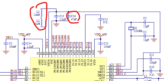
    Since you are using 1.8V as the power source then I dont think you need to include the DCDC components that is connected to DEC4_6. The DCDC is more efficient at higher voltage so when running at the low 1.8V the internal LDO is more or less just as efficient so the extra components and complexity is not super beneficial. 


    So these can be removed to save cost. 


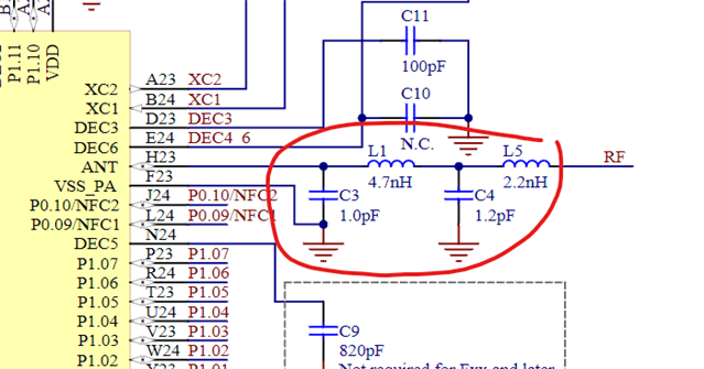
    The radio matching network is important to the performance of the device. With a bad network the output power of the device can be severely lacking and in addition the device might actually not pass certification criteria due to not good enough suppression of spurious emissions. 


    This should be copied from our design to get the best performance. Depending on the physical layout some minor tweaking can be done to the values to get the best results. 


    Other then that I the schematic looks ok, except for the HFXO crystal being 24MHz. But that you are aware of. 

    The value of the load caps can be calculated as well. So check you crystal datasheet. 

    The load capacitors, Ccap, are connected to the crystal and the values of the Ccap are given by the formula:

    Ccap = 2*CL – C_pcb – C_pin

    CL is the load capacitance of the crystal in use and can be found in the datasheet of the crystal.

    C_pcb + C_pin is approximately 4 pF for the HFXO pins and approximately 5 pF for the LFXO pins.


    For further reference you can have a look at this guide: https://devzone.nordicsemi.com/guides/hardware-design-test-and-measuring/b/nrf5x/posts/general-pcb-design-guidelines-for-nrf52-series 

    And always feel free to ask questions


    And yes if the crystal is rotated only 90 degrees then it will not work, the footprint is not enterally squared but have seen someone that mounted it wrong, so it can happen. Dont think that is the issue in your case. 


    Secondary, can you provide more info on the application and its version, what are you running?
    This might be some SW trickery or config issues and if you are not using our SDK then things might need to be adjusted. So testing with our SDK, using NCS version 2.6.1 or 2.7.0  will give us a good insight to what is failing if it is still failing when using one of our samples and should be relatively easy to set up and test. 


    Regards,
    Jonathan

  • Thank you for the info.  I was wondering about the capacitors on antenna circuit.  How do I know what those should be?  Could those cause the errors?

    I may have been off a little on the pcb capacitance.  The capacitors are set at 15 and maybe should be 16.  The CL is 10 of the crystal.  Do you think that is a problem and could cause the error?

    I am using the acconeer sdk, but also have ncs version 2.5.0.  I've been afraid to update it thinking it might not work with my code.  Should I update that?

    I'm just wondering why if it is a SW issue that it works with the xm126.  What would cause that?  I haven't really tried any NRF examples yet. Just the acconeer.  Not sure how to get the one on github that you posted to build.  I don't know where to put everything for that example or how to download it.  I'm not super familiar with github.  

    Mike

  • mchamberlain1980 said:
    I may have been off a little on the pcb capacitance.  The capacitors are set at 15 and maybe should be 16.  The CL is 10 of the crystal.  Do you think that is a problem and could cause the error?

    not a huge problem, should be useable as long as the layout does not include extra long traces and thus introduce more capacitance in the loop. The error that you are seeing is not related to the load cap offset. 


    mchamberlain1980 said:
    I am using the acconeer sdk, but also have ncs version 2.5.0.  I've been afraid to update it thinking it might not work with my code.  Should I update that?

    You can stick to 2.5.0, should not be a big issue. Just that 2.6 and 2.7 has some improvements and seem to be less confusing so I usually recommend those. 2.5.0 is fine. 


    mchamberlain1980 said:
    I'm just wondering why if it is a SW issue that it works with the xm126.  What would cause that?  I haven't really tried any NRF examples yet. Just the acconeer. 

    I dont know what the Acconeer SDK does so it can be that it mixes things up differently then what we do in our SDK som som of the configuration settings might not match. This is what I am suspecting. 


    mchamberlain1980 said:
    Not sure how to get the one on github that you posted to build.  I don't know where to put everything for that example or how to download it.  I'm not super familiar with github.  

    It is possible to have more then one instance of our SDK installed, so you can have your project in the 2.5.0 version but also download a different to test. 
    But the easy option is to just use our nRF Connect for Desktop app and use the toolchain manager to set up whatever you want. 

    here are som links, but feel free to ask about anything as well. 

    https://docs.nordicsemi.com/bundle/ncs-latest/page/nrf/installation/install_ncs.html#legacy_installation_with_toolchain_manager 

    We also have a guide\academy course for starting that takes you through lots of stuff, might be something you want to look at. 
    https://academy.nordicsemi.com/courses/nrf-connect-sdk-fundamentals/ This should provide you will all the get going knowledge.


    Will update with some info from the experts on the error code here.

    Regards,
    Jonathan

Related