This post is older than 2 years and might not be relevant anymore
More Info: Consider searching for newer posts

Designing trace antenna nRF51822-CFAC + BAL-NRF02D3, surrounding ground?

Hi there,

It isn't obvious from the reference layouts on the downloads page for nRF51822-CFAC if the ground plane is supposed to create a 50 Ohm trace going into the balun, or if there should be a ground pour around the antenna at all.

Should there be no ground around the antenna trace like this

image description

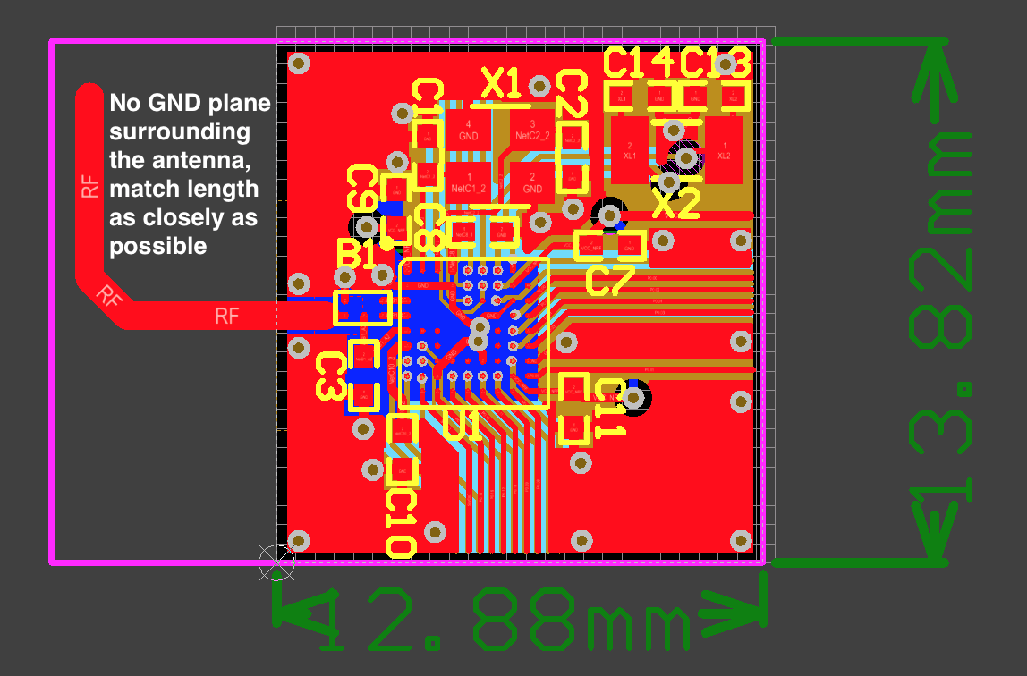
and then match the 1/4 wavelength antenna length as closely as possible?

Or, should there be a ground pour on the top and bottom layers like this

image description image description

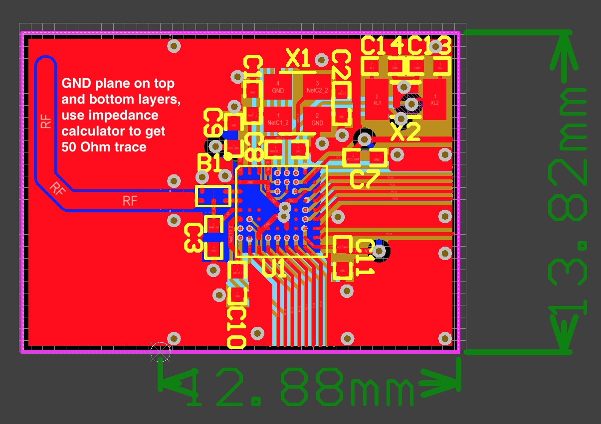
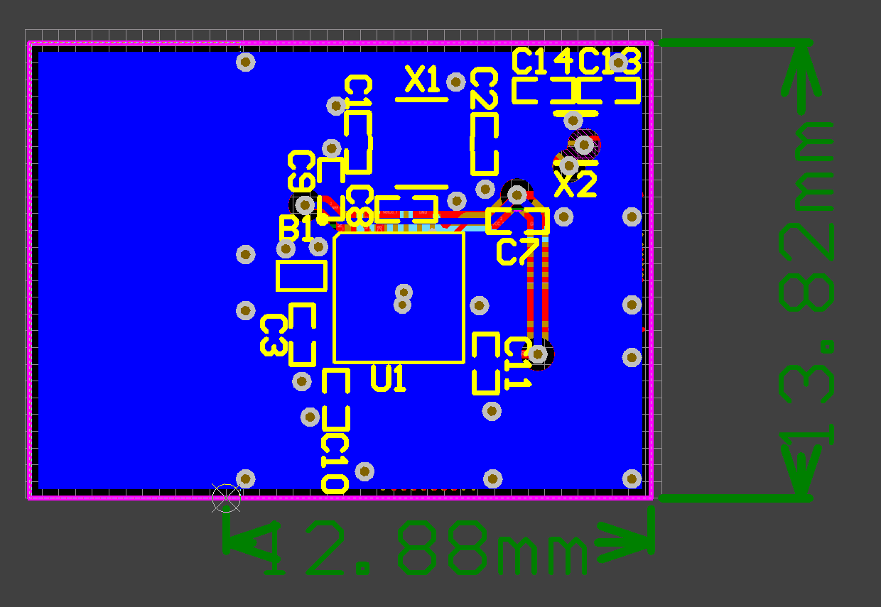
and then I can use an impedance calculating tool to calculate 50 Ohms on the antenna trace, based on the antenna distance from ground?

Finally, I think I should add a shunt component to the antenna trace near the balun for final tuning. Is that a good idea? Should I add an entire Pi network instead? Or nothing at all?

Thanks for your help, this forum is always extremely helpful. Brian

Parents
  • Hi,

    The RF part consists of the nRF side, the 50 Ohm transmission line and the antenna side. Only the nRF side is included in the reference layouts, as well as the beginning of the transmission line.

    For the complete layout the first image is correct. The antenna should not have ground around. The lack of ground is what makes the antenna an antenna (as opposed to a transmission line.) Antenna length is measured following the antenna from the edge of the ground plane. The ground plane edge should be the same on both (all) layers.

    You should make sure that the transmission line between the balun and the start of the antenna is 50 Ohm. For the width of the antenna anything around 2-3 mm is good.

    Tuning is required in both ends of the 50 Ohm transmission line. On the nRF end you should follow the reference layout closely (as is done on your images). On the antenna side, you can choose one of the following:

    1. Use one shunt capacitor and make the antenna longer than it should be. During the tuning process the antenna is physically shortened (this is done on a prototype board), and a good value is found for the shunt capacitor. Then the antenna length found during tuning is used for production boards.

    2. Use a pi network. Tuning is done by finding suitable components for the pi network. This is the only option if using an antenna that can not be physically altered for tuning purposes.

    For more on antenna tuning, se the nWP017 - Antenna tuning whitepaper.

    Regards, Terje

  • Hi,

    As per antenna design guidelines the antenna should not have ground around. Even reference design nRF51-DK has no ground around the antenna trace in all 4 layers. In such case how PCB fabricator can calculate antenna trace width for antenna to achieve 50ohm without reference plane. Please help me on this..

Reply Children
No Data
Related