Antenna match network design

Hi community,

I read these articles about match network for antenna:

General PCB design guidelines for nRF53 series - nRF5x - Hardware design, test and measuring - Nordic DevZone

Antenna matching - Nordic Q&A - Nordic DevZone - Nordic DevZone

my understanding: 

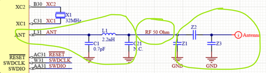
nRF5340 I'm using, to make the RF part works properly, three 50 Ohm values are important,

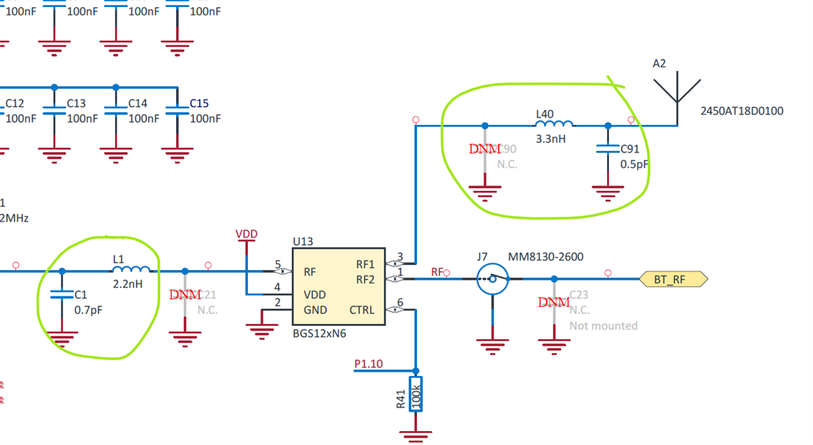
the first match network with 2.2nH inductor and 0.7pF capacitor is to make sure that the output impedance of the Chip is 50 Ohm,

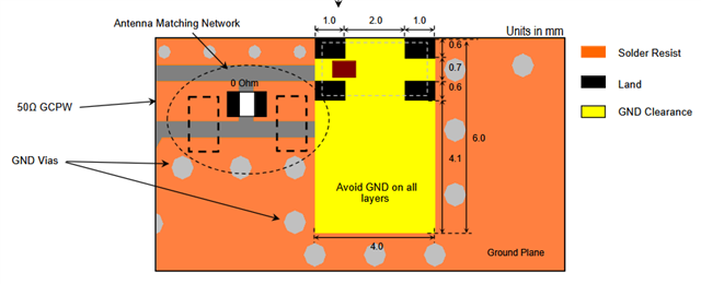
the second match network with Z1, Z2 and Z3 is to make sure that the impedance on side of antenna is also 50 Ohm,

and the transmission line is also 50 Ohm. 

My questions are: 

1. if the antenna itself and the transmission line, both already have the impedance 50 Ohm, is the second match network with Z1, Z2 and Z3 still needed? 

I see in the nRF7002 design the second match network is used? why?

2. if the impedance of transmission line is not 50 Ohm, but 104 Ohm, regardless of the optiaml performace, is it still possible to make the RF part functional? 

Thanks 

Danny

Parents
  • Hello,

    1. if the antenna itself and the transmission line, both already have the impedance 50 Ohm, is the second match network with Z1, Z2 and Z3 still needed? 

    The matching network at the nRF5340 radio's output is there to optimize the output power and filter out the harmonics. The 50-ohm coplanar waveguide is there to avoid losses between the radio output and the antenna.

    The antenna's matching network is there to match the antenna to the 50-ohm transmission line and minimize losses due to mismatch.

     2. ''if the impedance of transmission line is not 50 Ohm, but 104 Ohm, regardless of the optimal performance, is it still possible to make the RF part functional? ''

    How big the impact of a 104-ohm transmission line instead of a 50-ohm transmission line depends on the length of it. If it is very short, it may be that it doesn't have too much of an impact. But of course, our recommendation is definitely to use a 50-ohm coplanar waveguide. Otherwise, performance would be worse. 

    You can look at the antenna datasheet (https://www.johansontechnology.com/docs/967/2450AT18D0100001E_PLLZ5ar.pdf), then you will see 

    it is recommended to have an antenna-matching network.

    Thanks.

    BR

    Kazi

Reply
  • Hello,

    1. if the antenna itself and the transmission line, both already have the impedance 50 Ohm, is the second match network with Z1, Z2 and Z3 still needed? 

    The matching network at the nRF5340 radio's output is there to optimize the output power and filter out the harmonics. The 50-ohm coplanar waveguide is there to avoid losses between the radio output and the antenna.

    The antenna's matching network is there to match the antenna to the 50-ohm transmission line and minimize losses due to mismatch.

     2. ''if the impedance of transmission line is not 50 Ohm, but 104 Ohm, regardless of the optimal performance, is it still possible to make the RF part functional? ''

    How big the impact of a 104-ohm transmission line instead of a 50-ohm transmission line depends on the length of it. If it is very short, it may be that it doesn't have too much of an impact. But of course, our recommendation is definitely to use a 50-ohm coplanar waveguide. Otherwise, performance would be worse. 

    You can look at the antenna datasheet (https://www.johansontechnology.com/docs/967/2450AT18D0100001E_PLLZ5ar.pdf), then you will see 

    it is recommended to have an antenna-matching network.

    Thanks.

    BR

    Kazi

Children
Related